Supercharge Your Innovation With Domain-Expert AI Agents!

Friction nanometer generator and preparation method thereof

A nanogenerator and friction layer technology, applied in the direction of triboelectric generators, can solve the problems of affecting electric output performance and low triboelectric charge transfer amount, and achieve the effect of improving electric output performance, increasing charge transfer amount, and good application prospect.

Active Publication Date: 2021-01-15
SHENZHEN INST OF ADVANCED TECH
View PDF4 Cites 0 Cited by
  • Summary
  • Abstract
  • Description
  • Claims
  • Application Information

AI Technical Summary

Problems solved by technology

[0007] The purpose of the present invention is to overcome the above-mentioned deficiencies in the prior art, provide a frictional nanogenerator and its preparation method, aiming at solving the technical problem that the frictional charge transfer of the existing frictional nanogenerator is low, thus affecting the electrical output performance

Method used


Image

  • Friction nanometer generator and preparation method thereof
  • Friction nanometer generator and preparation method thereof

Examples


Embodiment 1

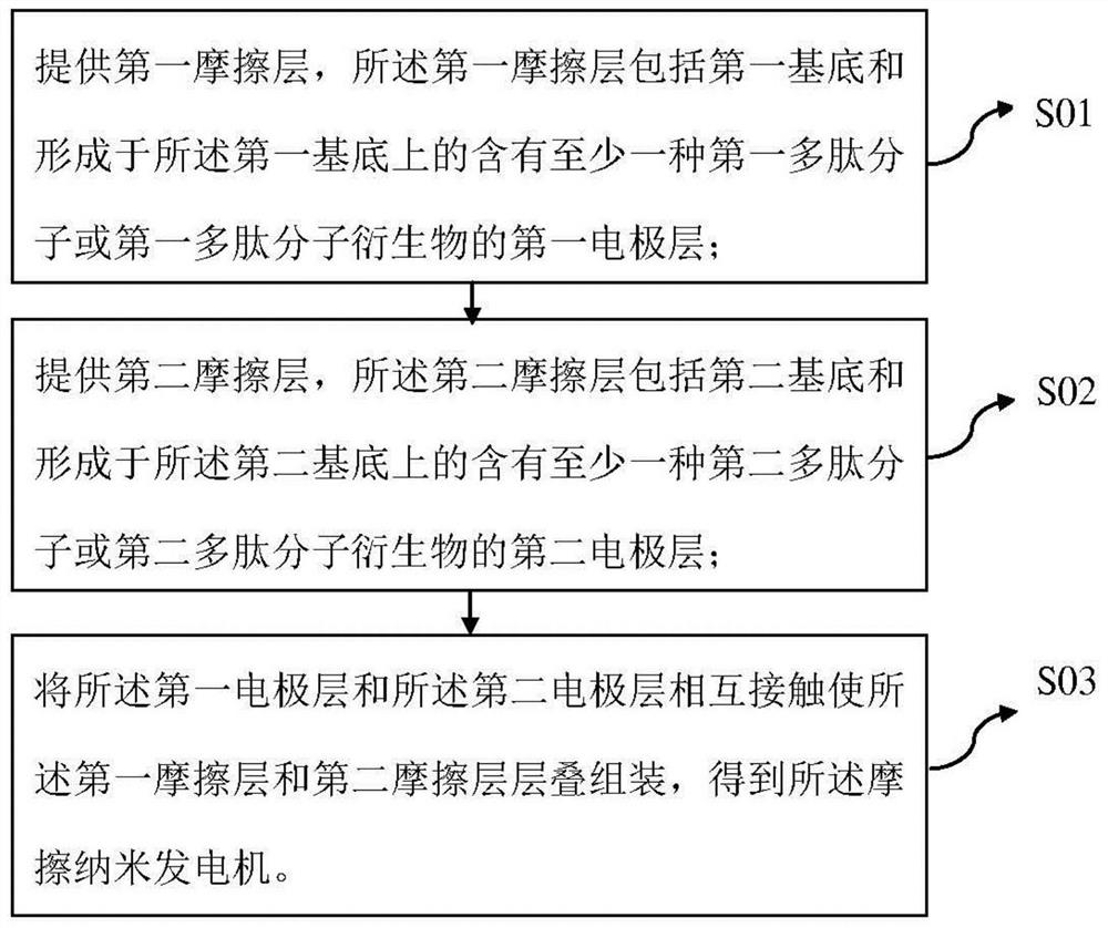
[0051] A kind of triboelectric nanogenerator, its preparation step comprises:

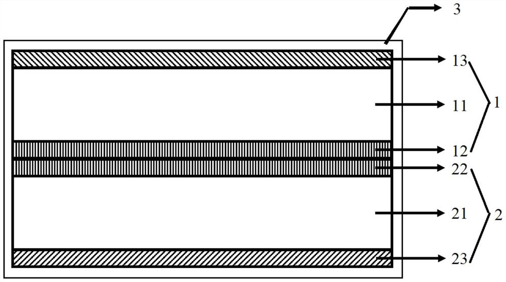
[0052]Firstly, the base layer and encapsulation layer materials are prepared. The first substrate and the second substrate layer of the triboelectric nanogenerator are respectively composed of polycaprolactone (PCL) and sodium alginate materials. The preparation method of the PCL membrane material is as follows: a certain amount of PCL polymer material is weighed and dissolved in a dichloromethane solution, and stirred evenly to form a homogeneous solution with a mass fraction of 10%. Then add the PCL solution into a clean glass plate, let it stand at room temperature to remove air bubbles, and then place it in a vacuum oven at 80°C for 12 hours to obtain a flat PCL film material for later use. Similarly, the preparation method of the sodium alginate membrane material is as follows: first configure the acetic acid solution with a volume fraction of 1%, then weigh a certain mass of sodium alginate ...

Embodiment 2

[0057] A kind of triboelectric nanogenerator, its preparation step comprises:

[0058] Firstly, the base layer and encapsulation layer materials are prepared. The first substrate and the second substrate layer of the triboelectric nanogenerator are respectively composed of polylactic acid-glycolic acid copolymer (PLGA) and polyvinyl alcohol (PVA) materials. The preparation method of the PLGA membrane material is as follows: a certain amount of PLGA polymer material is weighed and dissolved in a dichloromethane solution, and stirred evenly to form a homogeneous solution with a mass fraction of 10%. The PLGA solution was then added to a clean glass plate, left to stand at room temperature to remove air bubbles, and then placed in a vacuum oven at 80°C for 12 hours to obtain a flat PLGA film material for later use. Similarly, the preparation method of the PVA film material is as follows: Weigh a certain mass of PVA material and add it into deionized water, heat and stir evenly t...


PUM

PropertyMeasurementUnit
Thicknessaaaaaaaaaa
Thicknessaaaaaaaaaa
Thicknessaaaaaaaaaa

Abstract

The invention belongs to the technical field of implantable medical instruments and particularly relates to a friction nano-generator and a preparation method thereof. The friction nanometer generatorcomprises a first friction layer and a second friction layer which are in contact with each other, wherein the first friction layer comprises a first substrate and a first electrode layer which are arranged in a stacked mode, and the second friction layer comprises a second substrate and a second electrode layer which are arranged in a stacked mode, the first electrode layer contains at least onefirst polypeptide molecule or a first polypeptide molecule derivative, the second electrode layer contains at least one second polypeptide molecule or a second polypeptide molecule derivative, and the first electrode layer is adjacent to the second electrode layer. According to the friction nanometer generator, the polypeptide molecular material is used in the friction electrode layer, and the electron gain and loss capability between the first friction layer and the second friction layer can be differentiated, and thereby the charge transfer amount is improved, and the electrical output performance of the friction nano-generator is effectively improved.

Description

technical field [0001] The invention belongs to the technical field of implantable medical devices, and in particular relates to a friction nanogenerator and a preparation method thereof. Background technique [0002] Implantable Medical Devices (IMDs) have been widely used in clinical medicine due to their dexterity and convenience, real-time monitoring of patients' health status, and effective treatment of various emergencies. At present, the key factor restricting the development of active IMDs is mainly the energy supply problem. The energy for most active IMDs to maintain normal work mainly comes from their built-in batteries. Once the electric field energy is exhausted, implantable medical devices will face the dilemma of stopping work. At this time, a series of operations such as removing the device to replace the battery are required. cumbersome operations to continue the normal operation of the device. [0003] Currently, a large amount of electronic waste (E-wast...

Claims


Application Information

Patent Timeline
IPC IPC(8): H02N1/04
CPCH02N1/04
Inventor 江文朱朋莉孙蓉
Owner SHENZHEN INST OF ADVANCED TECH
Features
  • R&D
  • Intellectual Property
  • Life Sciences
  • Materials
  • Tech Scout
  • Unparalleled Data Quality
  • Higher Quality Content
  • 60% Fewer Hallucinations
Learn More