Indirect forming method for preparing metal product
A molding method and metal technology, applied in the field of additive manufacturing, can solve the problems of low density and lack of metallurgical bonding.
- Summary
- Abstract
- Description
- Claims
- Application Information
AI Technical Summary
Problems solved by technology
Method used
Image

Examples
Embodiment 1
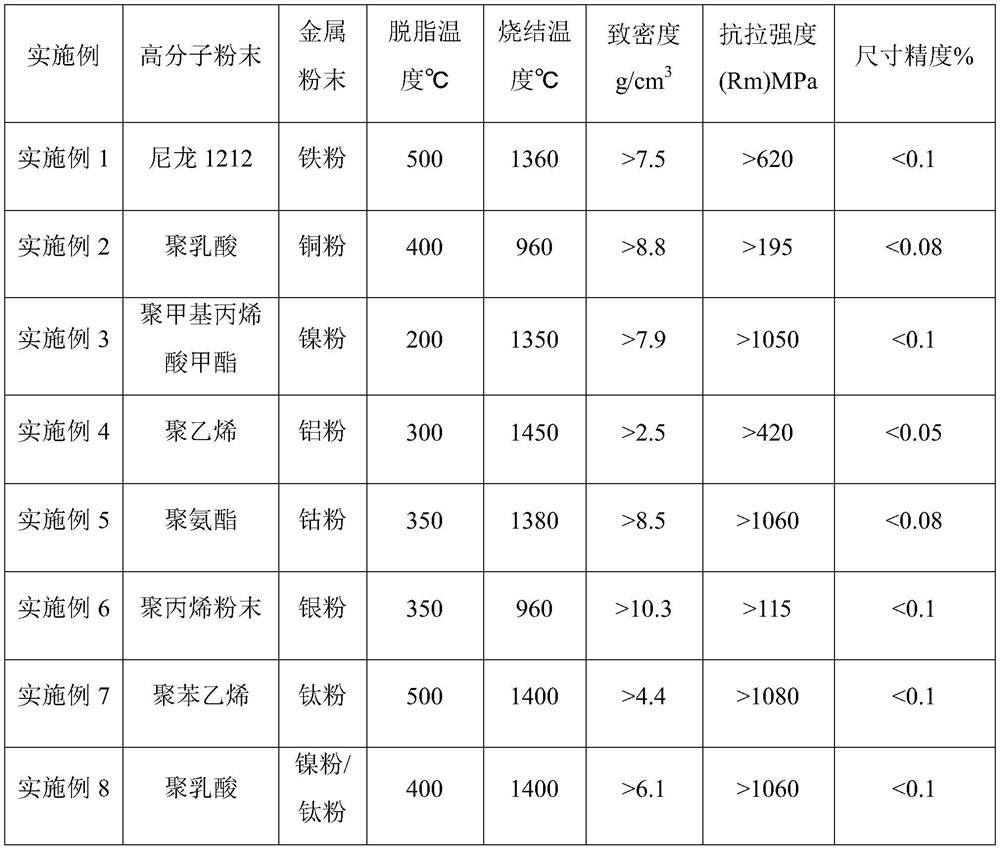
[0023] Step 1: Add 2 parts of nylon 1212 powder with an average particle size of 60 μm and 98 parts of iron powder with an average particle size of 25 μm into a stirring device, and physically mix them uniformly;
[0024] Step 2: Put the composite powder of iron powder and nylon 1212 prepared above into the selective laser sintering equipment that uses optical fiber with a wavelength of 400nm as the laser source. The maximum power range of the fiber laser is 500W, and the layer thickness is 0.15 mm, heat the composite powder of iron powder and nylon 1212 to a sintering temperature of 135°C, the melting point of nylon 1212 powder is 53°C, and then use a 300W laser to melt the powder, and the sintered line spacing is 0.3mm to prepare the iron prototype Sintered blanks.
[0025] Step 3: Degreasing sintering experiment Use an inert gas sintering furnace, put the iron prototype sintered blank into the sintering furnace, the debinding temperature of the first stage is 500°C, and the...
Embodiment 2
[0027] Step 1: Add 1 part of polylactic acid powder with an average particle size of 40 μm and 99 parts of copper powder with an average particle size of 1 μm into a stirring device for physical mixing;
[0028] Step 2: Put the composite powder of copper powder and polylactic acid prepared above into the selective laser sintering equipment that uses optical fiber with a wavelength of 500nm as the laser source. The maximum power range of the fiber laser is 2000W, and the layer thickness is 0.1 mm, heat the composite powder of copper powder and polylactic acid to a sintering temperature of 100°C, the melting point of the polylactic acid powder is 55°C, and then use a laser with a sintering power of 2000W to melt the powder, and the sintered line spacing is 0.5mm to prepare a copper prototype Sintered blanks.
[0029] Step 3: Degreasing sintering experiment Use an inert gas sintering furnace, put the copper prototype sintered blank into the sintering furnace, the first stage degr...
Embodiment 3
[0031] Step 1: Add 2 parts of polymethyl methacrylate powder with an average particle size of 50 μm and 98 parts of nickel powder with an average particle size of 10 μm into a stirring device for physical mixing;
[0032] Step 2: Put the composite powder of nickel powder and polymethyl methacrylate prepared above into the selective laser sintering equipment using the optical fiber with a wavelength of 600nm as the laser source. The maximum power range of the fiber laser is 100W. The layer thickness is 0.12mm, the composite powder of nickel powder and polymethyl methacrylate is heated to the sintering temperature of 90°C, the melting point of polymethyl methacrylate powder is 60°C, and then the powder is melted with a sintering power of 800W laser , the sintered line spacing is 0.4mm to prepare the nickel prototype sintered blank.
[0033] Step 3: Degreasing sintering experiment Use an inert gas sintering furnace, put the nickel prototype sintered blank into the sintering furna...
PUM
| Property | Measurement | Unit |
|---|---|---|
| Particle size | aaaaa | aaaaa |
Abstract
Description
Claims
Application Information
 - Generate Ideas
- Intellectual Property
- Life Sciences
- Materials
- Tech Scout
- Unparalleled Data Quality
- Higher Quality Content
- 60% Fewer Hallucinations
Browse by: Latest US Patents, China's latest patents, Technical Efficacy Thesaurus, Application Domain, Technology Topic, Popular Technical Reports.
© 2025 PatSnap. All rights reserved.Legal|Privacy policy|Modern Slavery Act Transparency Statement|Sitemap|About US| Contact US: help@patsnap.com