Solid oxide fuel cell system and solid oxide fuel cell power generation method

A fuel cell system and solid oxide technology, applied in solid electrolyte fuel cells, fuel cells, fuel cell additives, etc., can solve the problems of large power consumption and low single-pass conversion rate, improve power generation efficiency, and simplify the system process. , The effect of high heat exchange efficiency

Inactive Publication Date: 2021-02-02
CHNA ENERGY INVESTMENT CORP LTD +1
View PDF8 Cites 1 Cited by
  • Summary
  • Abstract
  • Description
  • Claims
  • Application Information

AI Technical Summary

Problems solved by technology

[0006] The purpose of the present invention is to overcome the defects that the single-pass conversion rate and / or power consumption in the prior art are relatively large

Method used


Image

  • Solid oxide fuel cell system and solid oxide fuel cell power generation method
  • Solid oxide fuel cell system and solid oxide fuel cell power generation method
  • Solid oxide fuel cell system and solid oxide fuel cell power generation method

Examples


Embodiment 1

[0090] This embodiment operates under the condition that the power generation capacity of the electric stack is 1kW. The specific operation process includes:

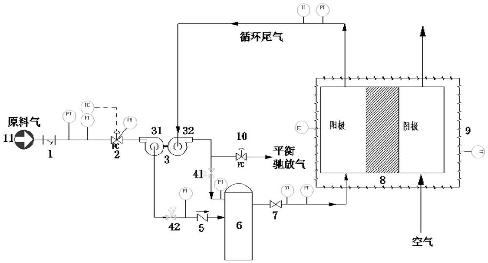
[0091] Synthesis gas from feed gas source 11 (specifically including: N 2 1.12% by volume, O 2 0.02% by volume, H 2 61.78vol%, CO 36.71vol%, CO 2 0.24% by volume and CH 4 0.13 volume %) enters in the turbine 31 of turbocharging device 3 after passing through filter 1 and flow meter 2 successively, and the temperature, pressure and flow of feed gas are measured at the inlet of this turbine 31, and are recorded in Table 1. The feed gas drives the turbine 31 to rotate, thereby driving the coaxial impeller 32 to also rotate. The rotation of the impeller 32 generates negative pressure to suck the anode tail gas generated by the electric stack 8 . The raw gas passing through the turbine 31 enters the mixing tank 6 after passing through the anode tail gas pressure regulating valve 41 and the one-way valve 5 successiv...

Embodiment 2

[0098] This embodiment is carried out under the condition that the generating capacity of the electric stack is 4kW, and the specific operation process is carried out according to the embodiment 1.

[0099] The specific operating parameters are shown in Table 2.

[0100] After testing and calculation,

[0101] The power generation efficiency of the system is 55.8%;

[0102] The emission rate of pollutant gas in the exhaust gas (gas that undergoes balance relaxation at the balance valve 10 ) was 14.1% by volume.

[0103] Table 2

[0104]

Embodiment 3

[0106] According to the method of Example 1, the difference is that the balance valve 10 is used to adjust the amount of anode tail gas that is balanced and relaxed, so that the operating parameters are as shown in Table 3.

[0107] After testing and calculation,

[0108] The power generation efficiency of the system is 55.4%;

[0109] The emission rate of pollutant gas in the exhaust gas (gas that undergoes balance relaxation at the balance valve 10 ) was 14.5% by volume.

[0110] table 3

[0111]


PUM


Abstract

The invention relates to the field of solid oxide fuel cells, in particular to a solid oxide fuel cell system and a solid oxide fuel cell power generation method. The system comprises a raw material gas source (11), a mixing tank (6), an electric pile (8) and a turbocharging device (3), wherein the turbocharging device (3) is communicated with the raw material gas source (11) and the mixing tank (6) and is communicated with the electric pile (8) and the mixing tank (6). According to the system and the method, the power generation efficiency of a battery can be remarkably improved, and the content of pollution gas in exhaust gas is reduced.

Description

technical field [0001] The invention relates to the field of solid oxide fuel cells, in particular to a solid oxide fuel cell system and a solid oxide fuel cell power generation method. Background technique [0002] A solid oxide fuel cell (Solid Oxide Fuel Cell, SOFC for short) is a power generation device that converts the chemical energy of hydrocarbons into electrical energy. SOFC batteries are mainly composed of porous anode, electrolyte, and porous cathode. Hydrocarbons are fed into the porous anode, air is fed into the porous cathode, and the electrolyte is yttria stabilized zirconia (YSZ) ceramics. At high temperature, the oxygen ions in the porous cathode side are transferred to the hydrocarbons in the porous anode side through the ceramic electrolyte, and hydrogen, CO, CH 4 etc. react to produce water, CO 2 , hydrogen, CO, CH 4 Etc. anode tail gas; the electron migration of the cathode and anode forms a current to generate electricity. [0003] At present, the...

Claims


Application Information

Patent Timeline
Patent Type & Authority Applications(China)
IPC IPC(8): H01M8/04014H01M8/04089H01M8/04111H01M8/04746H01M8/0662H01M8/12H01M8/1253
CPCH01M8/04014H01M8/04097H01M8/04111H01M8/04761H01M8/0662H01M8/12H01M8/1253H01M2008/1293Y02E60/50
Inventor 闫学良巴黎明李萍萍常彬杰李轩罗峰姚金松孙永伟龙银花高星矫卫东
Owner CHNA ENERGY INVESTMENT CORP LTD
Why Eureka
Try Eureka