EPR thermal shrinkage cable terminal internal defect detection system and detection method thereof

A heat-shrinkable cable, internal defect technology, used in measuring devices, material analysis by optical means, instruments, etc., can solve problems such as harsh application conditions, discharge breakdown, and large environmental temperature effects, and achieve good promotion prospects and improve. The effect of signal-to-noise ratio and strong penetration

Pending Publication Date: 2021-02-05
LANZHOU JIAOTONG UNIV
View PDF0 Cites 3 Cited by
  • Summary
  • Abstract
  • Description
  • Claims
  • Application Information

AI Technical Summary

Problems solved by technology

However, during the installation process, it is easily affected by factors such as the installation process, operating conditions, and external force damage; in the later use and long-term operation, its application scenarios are even more diverse, and it is often in harsh application conditions.
Therefore, in the long-term operation, due to the joint action of rapid cold and heat alternation, transient overvoltage shock and long-term high-frequency vibration, the internal insulation layers are separated, resulting in micro air gaps and partial discharges; as the air gap continues Increase and gradually form a discharge channel, and the internal insulating layer material will be decomposed due to discharge ablation; with the further growth and expansion of the air gap and the continuous accumulation of discharge ablation carbides, the degree of discharge will continue to intensify, the air gap will continue to grow, and eventually form a through hole. line discharge channel, resulting in discharge breakdown
[0003] At present, the detection methods of EPR heat-shrinkable cable terminals are limited to the dielectric loss tangent angle test, partial discharge detection, infrared temperature measurement, etc. used in maintenance at all levels. Defects cannot be detected, and it is difficult to meet th

Method used


Image

  • EPR thermal shrinkage cable terminal internal defect detection system and detection method thereof
  • EPR thermal shrinkage cable terminal internal defect detection system and detection method thereof

Examples


Embodiment

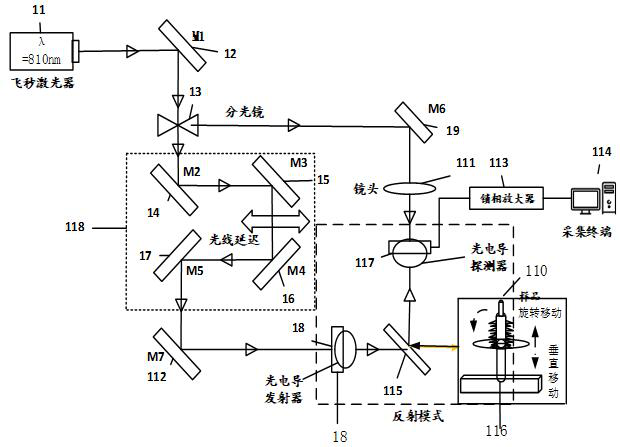
[0053] Such as Figure 1-2 As shown, an EPR heat-shrinkable cable terminal internal defect detection system includes: a femtosecond laser 11 and a beam splitter 13 arranged from left to right along the terahertz pulse path, a detection optical system and an excitation system arranged in parallel behind the beam splitter 13 The optical path system also includes a lock-in amplifier 113 and an acquisition terminal 114 connected to each other;

[0054] The detection optical path system includes a delay control unit 118, a photoconductive emitter 18, a reflector 8 115, and a two-degree-of-freedom fast-moving platform 116 arranged sequentially along the optical path from left to right; a photoconductive detector 117 is arranged above the reflector 8 115 The two-degree-of-freedom platform 116 is provided with the sample 110 of the EPR heat-shrinkable cable, and the sample 110 can move freely up and down on the vertical direction of the two-degree-of-freedom platform 116 and freely ro...


PUM

PropertyMeasurementUnit
Heart wavelengthaaaaaaaaaa
Pulse widthaaaaaaaaaa

Abstract

The invention discloses an EPR thermal shrinkage cable terminal internal defect detection system and a detection method thereof, belongs to the technical field of high voltage and insulation, and aimsto solve the problems of poor generalization performance, poor penetrability, great environmental temperature influence, damage to a detected object and the like. The system comprises a femtosecond laser, a spectroscope, a detection light path system, an excitation light path system, a lock-in amplifier and an acquisition terminal, wherein the femtosecond laser and the spectroscope are arranged from left to right along a terahertz pulse path, the detection light path system and the excitation light path system are arranged behind the spectroscope in parallel, and the lock-in amplifier and theacquisition terminal are connected with each other. The method comprises the steps of: sample preparation and installation, defect detection, data collection and processing and result application. The combination of the system and the method is the widening of the application of the terahertz nondestructive visual detection technology to an EPR thermal shrinkage cable terminal; the unique structure and the method are combined, the terahertz time-domain spectral characteristics of the internal defects of the EPR thermal shrinkage cable terminal can be clearly established; and finally, the reverse application is carried out, so that the nondestructive visual detection of the internal defects of a composite cable is realized.

Description

technical field [0001] The invention belongs to the technical field of high voltage and insulation, and in particular relates to an internal defect detection system and a detection method of an EPR heat-shrinkable cable terminal. Background technique [0002] EPR heat-shrinkable cable terminals have been widely used in medium and low voltage power systems and traction power supply systems due to their small size, light weight, easy installation, and wide application range. However, during the installation process, it is easily affected by factors such as the installation process, operating conditions, and external force damage; in the later use and long-term operation, its application scenarios are even more diverse, and it is often in harsh application conditions. . Therefore, in the long-term operation, due to the joint action of rapid cold and heat alternation, transient overvoltage shock and long-term high-frequency vibration, the internal insulation layers are separate...

Claims


Application Information

Patent Timeline
IPC IPC(8): G01N21/3586
CPCG01N21/3586
Inventor 李帅兵曹炳磊康永强豆利龙杨兴祖董海鹰
Owner LANZHOU JIAOTONG UNIV
Why Eureka
Try Eureka