Anisotropic plasmon resonant cavity graphene polarization detector and design method

A plasmonic and anisotropic technology, applied in the direction of measuring the polarization of light, instruments, measuring devices, etc., can solve the problems of large volume, low sensitivity, complex structure of the optical path segmentation method, etc.

Inactive Publication Date: 2021-03-16
SHANGHAI INST OF TECHNICAL PHYSICS - CHINESE ACAD OF SCI
View PDF2 Cites 2 Cited by
  • Summary
  • Abstract
  • Description
  • Claims
  • Application Information

AI Technical Summary

Problems solved by technology

However, these methods have some disadvantages, such as the slow speed and low sensitivity of the polarizer rotation method, the complex structure and poor alignment accuracy of the optical path division method, and both are large in size
Moreover, the use of complex optical paths and various optical devices affects the luminous flux and reduces the sensitivity of the detector.

Method used


Image

  • Anisotropic plasmon resonant cavity graphene polarization detector and design method
  • Anisotropic plasmon resonant cavity graphene polarization detector and design method
  • Anisotropic plasmon resonant cavity graphene polarization detector and design method

Examples


Embodiment example

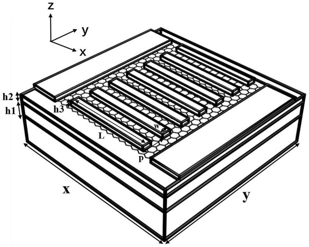
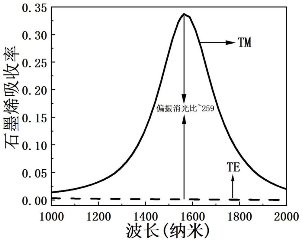
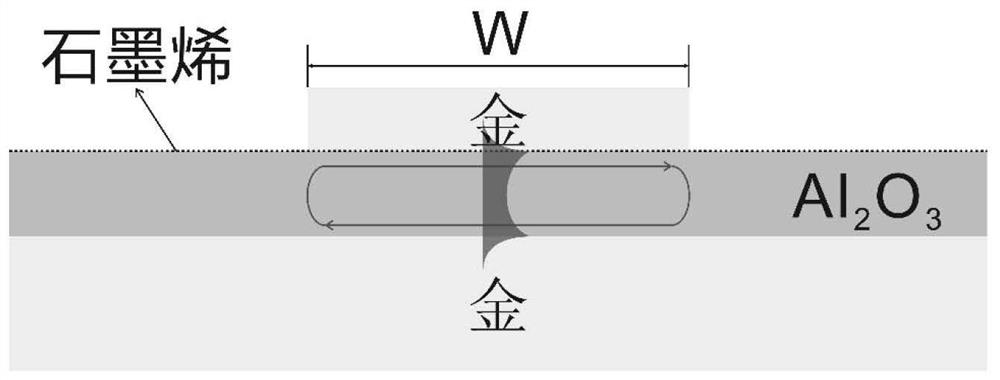
[0027] The resonance wavelength of the graphene phototransistor integrated in the plasmonic resonator cavity of this embodiment is 1.55 μm, the metal reflective surface and the metal grid are made of gold, and the dielectric spacer layer is made of Al 2 o 3 , and covered with a single layer of graphene, and finally covered with metal bars on the graphene. The size of the structure obtained through electromagnetic simulation optimization is: x=0.75μm, y=0.75μm, w=242nm, p=588nm, L=0.45μm, h 1 =100nm, the thickness of the dielectric spacer layer 3 obtained through simulation optimization is h 2 = 30nm Al 2 o 3 . The material of the metal bar grid layer 4 is gold, and the thickness is h 3 = 50nm, including 10nm thick Cr and 40nm thick Au. figure 2 is the absorption spectrum of graphene under the irradiation of the incident light (TM wave) with the polarization direction perpendicular to the metal grid and the incident light (TE wave) with the polarization direction paralle...


PUM


Abstract

The invention discloses an anisotropic plasmon resonant cavity graphene polarization detector and a design method. The anisotropic plasmon resonant cavity graphene polarization detector structurally comprises a substrate material layer, a metal reflecting layer, a dielectric spacer layer, a graphene layer and a metal bar grid layer. The polarization detector is based on a plasmon resonant cavity structure, a plasmon waveguide mode is formed between a top metal surface and a bottom metal surface, the cavity length of a resonant cavity is defined by a top metal boundary, and when the wavelengthand the cavity length meet the interference phase length condition, the mode reaches a resonance state, and a local strong light field of a deep sub-wavelength scale is realized. Due to anisotropy ofthe metal strip structure, the mode can only be excited by incident light with the polarization direction perpendicular to the metal strip grid, and light absorption and light response of graphene canbe improved; most of incident light with the polarization direction parallel to the metal bar grid is reflected, absorption and photoresponse of graphene cannot be effectively excited, and thereforethe high polarization extinction ratio and photoresponse enhancement of the selected polarization state are achieved.

Description

technical field [0001] The invention relates to the fields of nanophotonics, polarization detection, two-dimensional material light detection, etc., and specifically relates to a graphene polarization detector enabled by an anisotropic plasmon resonator that realizes high polarization extinction ratio. Background technique [0002] Besides intensity and wavelength, polarization is another major physical quantity related to light fields. Polarization detection provides a new dimension for feature recognition, revealing many unique and important object information, and polarization detection is a powerful tool to enhance object information recognition. Graphene-based photodetectors have attracted extensive interest due to their excellent properties, such as broadband photoresponse from ultraviolet to terahertz, fast response time, and excellent mechanical elasticity and strength. However, pristine graphene, like most light-detecting materials, cannot resolve polarization stat...

Claims


Application Information

Patent Timeline
Patent Type & Authority Applications(China)
IPC IPC(8): G01J4/00
CPCG01J4/00
Inventor 周靖余宇郭尚坤嵇兆煜代旭储泽世陈效双蔡清元李方哲兰梦珂邓杰
Owner SHANGHAI INST OF TECHNICAL PHYSICS - CHINESE ACAD OF SCI
Why Eureka
Try Eureka