Check patentability & draft patents in minutes with Patsnap Eureka AI!

Laser cladding device and method based on machine vision and ultrasonic vibration

A technology of laser cladding and ultrasonic vibration, which is applied in the coating process of metal materials, coating, etc., can solve the problems that the vibration angle cannot be adjusted, the size of the molten pool cannot be directly obtained, and the ultrasonic vibration cannot directly affect the laser molten pool. Achieve the effect of reducing energy loss and improving the quality of cladding layer

Pending Publication Date: 2021-04-02
XINJIANG UNIVERSITY
View PDF5 Cites 1 Cited by
  • Summary
  • Abstract
  • Description
  • Claims
  • Application Information

AI Technical Summary

Problems solved by technology

[0005] The present invention provides a laser cladding device and method based on machine vision and ultrasonic vibration, which overcomes the above-mentioned deficiencies in the prior art, and can effectively solve the problem that the ultrasonic vibration existing in the existing laser cladding device cannot directly act on the laser molten pool , and the vibration angle cannot be adjusted
Further solve the problem that the existing laser cladding device cannot directly obtain the size of the molten pool

Method used


Image

  • Laser cladding device and method based on machine vision and ultrasonic vibration
  • Laser cladding device and method based on machine vision and ultrasonic vibration
  • Laser cladding device and method based on machine vision and ultrasonic vibration

Examples


Embodiment 1

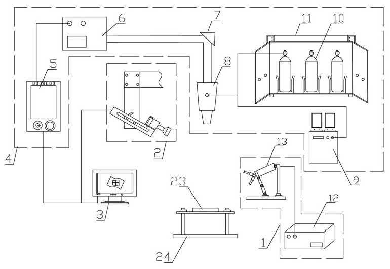
[0046] Embodiment 1: as attached figure 1 As shown, a laser cladding device based on machine vision and ultrasonic vibration is disclosed, including an ultrasonic vibration mechanism 1, an industrial camera mechanism 2, an adjustment and control mechanism 3, and a laser cladding mechanism 4;

[0047] The ultrasonic vibration mechanism 1 is used to apply ultrasonic vibration to the laser molten pool 23;

[0048] The industrial camera mechanism 2 is used to obtain the geometric features of the laser melting pool, wherein the geometric features of the laser melting pool include melting width, melting height and melting depth;

[0049] The adjustment and control mechanism 3 is used to communicate with the laser cladding mechanism 4 and the industrial camera mechanism 2; construct the pose adjustment program during laser cladding; realize laser cladding based on the fuzzy PID control strategy according to the geometrical characteristics of the laser molten pool Adaptive tuning of ...

Embodiment 2

[0055] Embodiment 2: as attached figure 2 As shown, a laser cladding device based on machine vision and ultrasonic vibration is disclosed, wherein the adjustment and control mechanism 3 includes a pose adjustment construction unit, a parameter adaptive tuning unit and a data export unit;

[0056] Pose adjustment construction unit, "discrete and layer" preset complex parts, and build a pose adjustment program for laser cladding;

[0057] Parameter self-adaptive tuning unit, based on the fuzzy PID control strategy, realizes self-adaptive tuning of laser cladding process parameters according to the geometric characteristics of the laser molten pool;

[0058] The data export unit is used to export data to the industrial camera mechanism 2 and the laser cladding mechanism 4, wherein the data includes parameters, programs and control instructions.

[0059] In the above technical solution, the adjustment and control mechanism 3 can be the main control computer, which is equipped wi...

Embodiment 3

[0061] Embodiment 3: as attached figure 1 As shown, a laser cladding device based on machine vision and ultrasonic vibration is disclosed, wherein the laser cladding mechanism 4 includes a laser control board 5, a fiber laser 6, a laser reflector 7, a synchronous powder feeding laser head 8, and a powder feeder 9 and a plurality of protective gas cylinders 10;

[0062] The adjustment and control mechanism 3 is connected to the laser control board 5, and the laser control board 5, the fiber laser 6, the laser reflector 7, and the synchronous powder feeding laser head 8 are connected in sequence; the laser control board 5 receives the data sent by the adjustment and control mechanism 3, and controls the The laser emitter emits laser light, and the laser light is emitted by the synchronous powder feeding laser head 8 through the laser reflector 7 . Among them, the laser control board 5 acts as a bridge, receiving data such as parameters, programs and control instructions sent by...


PUM


Abstract

The invention relates to the technical field of laser cladding, in particular to a laser cladding device and method based on machine vision and ultrasonic vibration. The device comprises an ultrasonicvibration mechanism, an industrial camera mechanism, an adjustment and control mechanism and a laser cladding mechanism, wherein the ultrasonic vibration mechanism is used for applying ultrasonic vibration to a laser molten pool, the industrial camera mechanism is used for acquiring geometrical morphology characteristics of the laser molten pool, the adjustment and control mechanism is used for constructing a pose adjustment program during laser cladding and realizing self-adaptive setting of laser cladding process parameters based on a fuzzy PID control strategy, and the laser cladding mechanism is used for conducting laser cladding on the laser molten pool according to the laser cladding process parameters, and realizing precise forming of complex parts. According to the device, size information of the molten pool is acquired by means of the industrial camera mechanism, real-time self-adaptive setting of the laser cladding process parameters is realized based on the machine vision and a PID controller, layer-by-layer cladding is conducted on complex parts till accurate forming is realized, and an ultrasonic field is directly applied to the laser molten pool, so that the qualityof a cladding layer can be obviously improved under a low-energy input condition, and the energy loss is reduced.

Description

technical field [0001] The invention relates to the technical field of laser cladding, and relates to a laser cladding device and method based on machine vision and ultrasonic vibration. Background technique [0002] As the core component of an aero-engine, the space curved impeller has a complex cavity structure, and its surface roughness and machining accuracy have a great influence on the performance of the impeller. With the increase of the thrust-to-weight ratio of the aero-engine (≥10), the temperature of the gas continues to increase (≥900°C), and the requirements for the working performance of the space curved impeller are becoming more and more stringent. At present, the processing methods of superalloy curved surface impellers include: CNC milling, precision casting, electrochemical machining, etc. However, CNC milling technology is difficult to process in a small space, and the production cost is high; the casting preparation process is complicated, and the yield...

Claims


Application Information

Patent Timeline
IPC IPC(8): C23C24/10C21D10/00
CPCC23C24/10C21D10/00
Inventor 孙文磊肖奇杨凯欣邢学峰周浩南陈子豪陆靖
Owner XINJIANG UNIVERSITY
Features
  • R&D
  • Intellectual Property
  • Life Sciences
  • Materials
  • Tech Scout
  • Unparalleled Data Quality
  • Higher Quality Content
  • 60% Fewer Hallucinations
Learn More