Centralized energy consumption device topology of flexible direct-current power transmission system

A technology for energy-consuming devices and power transmission systems, which can be used in output power conversion devices, wind power generation, electrical components, etc., and can solve problems such as poor reliability.

Pending Publication Date: 2021-04-02
TBEA XIAN FLEXIBLE TRANSMISSION & DISTRIBUTIONCO +1
View PDF0 Cites 2 Cited by
  • Summary
  • Abstract
  • Description
  • Claims
  • Application Information

AI Technical Summary

Problems solved by technology

[0003] Aiming at the problem of single controllable semiconductor devices in the semiconductor switch sub-module in the prior art, if a single controllable semiconductor switch refuses to move, there is no device to replace the work, so that the switch sub-module cannot be bypassed and exits the system operation; the present invention Provide a centralized energy consumption device topology of a flexible direct current transmission system, the device topology is simple, easy to operate, and effectively solve the problem of poor reliability caused by the simplification of controllable semiconductor devices in the switch assembly

Method used


Image

  • Centralized energy consumption device topology of flexible direct-current power transmission system
  • Centralized energy consumption device topology of flexible direct-current power transmission system
  • Centralized energy consumption device topology of flexible direct-current power transmission system

Examples


Embodiment 1

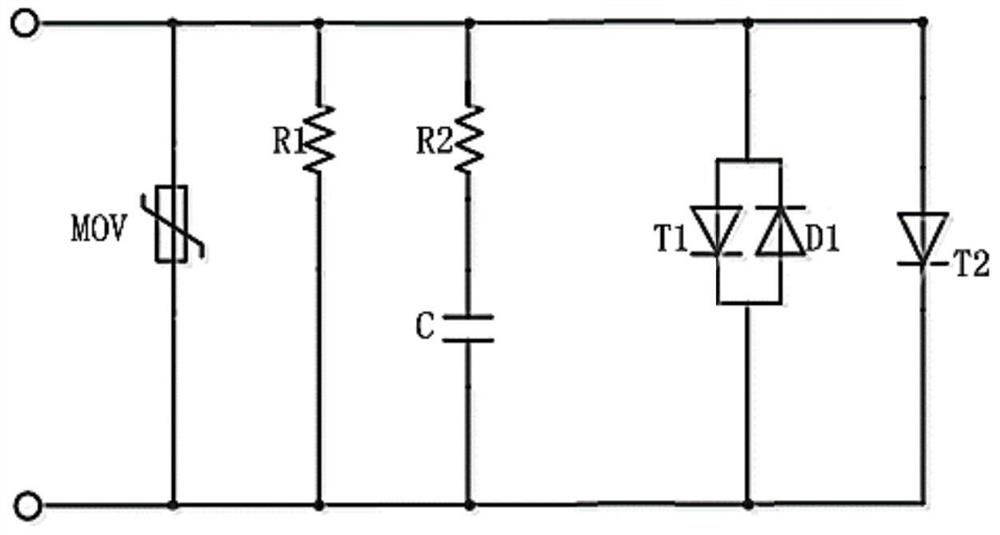
[0038] according to figure 2 As shown, one switch assembly m is provided with a switch sub-module, and a switch sub-module includes a first controllable semiconductor device T1, a second controllable semiconductor device T2, an absorbing resistor R1, a voltage equalizing resistor R2, a voltage limiter MOV, diode D1 and snubber capacitor C;

[0039] Wherein the first controllable semiconductor device T1 is preferably an integrated gate commutated thyristor IGCT, and the second controllable semiconductor device T2 is preferably a thyristor.

[0040] The anode of the integrated gate commutated thyristor IGCT is connected to the negative pole of D1 of the diode, and the cathode of the integrated gate commutated thyristor IGCT is connected to the positive pole of the diode. The anode of the thyristor is connected to the anode of the integrated gate commutated thyristor IGCT, and the cathode of the thyristor is connected to the cathode of the integrated gate commutated thyristor I...

Embodiment 2

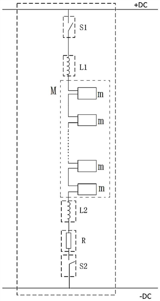
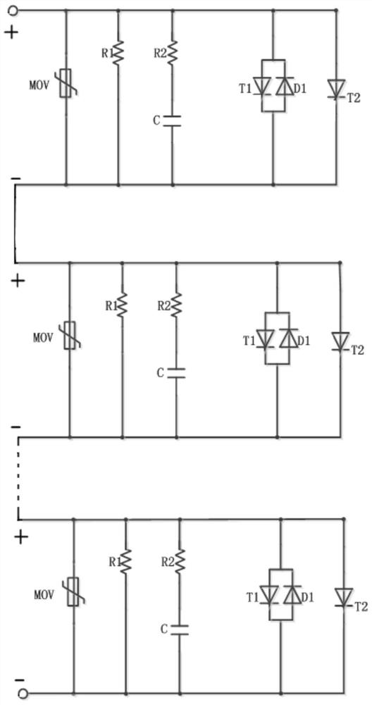
[0043] according to image 3 As shown, the present embodiment is different from Embodiment 1. The switch sub-module is formed by connecting more than two in series, and the negative port of the switch sub-module is connected to the positive port of the adjacent switch sub-module; and so on, composed of multiple The switch sub-modules are cascaded to form the switch assembly m; the advantage of cascading several switch assemblies m to form the energy consumption device M is that structural components can be saved, and the cost of the energy consumption device can be reduced compared with Embodiment 1.


PUM


Abstract

According to the flexible DC power transmission system centralized energy consumption device topology provided by the invention, the second controllable semiconductor device T2 is additionally arranged on the switch sub-module, so a problem that the controllable semiconductor device in the semiconductor switch is simplified is effectively solved, and a problem that the semiconductor switch cannotbe used when a single controllable semiconductor switch refuses to operate is avoided; the second controllable semiconductor device T2 is added to effectively replace the rejected first controllable semiconductor device T1, sustainability of the semiconductor switch is improved, effective bypass of the switch sub-module is ensured, and after the controllable semiconductor device T1 breaks down, the MOV cannot be exploded. When the offshore wind power flexible direct-current power transmission system has an alternating-current fault on a land station, the energy release device can consume surplus energy, and the fault is prevented from being diffused to an offshore system; direct current is monitored, and surplus energy is discharged; DC overvoltage is reliably suppressed by presetting a target DC voltage; emergency power control becomes possible, and more control is provided for operation and maintenance personnel.

Description

technical field [0001] The invention relates to the technical field of flexible direct current transmission, in particular to a topology of a centralized energy consumption device of a flexible direct current transmission system. Background technique [0002] With the development of offshore flexible DC transmission technology, the reliability of power transmission has gradually become a technical indicator that cannot be ignored. For system AC faults, adding energy-consuming devices has become an executable fault ride-through solution. At present, there are two main technical routes for energy-consuming devices, distributed and centralized. Distributed is consistent with the technical route of the converter valve, and its implementation is relatively simple. Centralized versus distributed technology does not adopt the method of connecting multiple modules in series, but adopts the method of connecting multiple switch components in series, and adding some protection and vol...

Claims


Application Information

Patent Timeline
Patent Type & Authority Applications(China)
IPC IPC(8): H02M1/32H02J3/36
CPCH02J3/36H02M1/32Y02E10/76Y02E60/60
Inventor 张明露林卫星盛俊毅靳广超张红波张新刚
Owner TBEA XIAN FLEXIBLE TRANSMISSION & DISTRIBUTIONCO
Why Eureka
Try Eureka