
Device and method for in-situ laser drilling sampling and solder sealing of small pipe

A laser drilling and welding sealing technology, which is applied in laser welding equipment, welding equipment, metal processing equipment, etc., can solve the problems of poor observation effect of lighting source, not enough to solve the problems of microhole processing-sampling-sealing, lack, etc. , to achieve the effect of ensuring continuous reliable service, large aspect ratio and small heat-affected zone

Inactive Publication Date: 2021-04-09
MATERIAL INST OF CHINA ACADEMY OF ENG PHYSICS
View PDF5 Cites 2 Cited by
  • Summary
  • Abstract
  • Description
  • Claims
  • Application Information

AI Technical Summary

Problems solved by technology

[0003] In some specific engineering fields, there has been an application demand for using ultrafast lasers for near-non-destructive micro-nano drilling sampling analysis, and then for in-situ laser sealing and welding of microholes. The above-mentioned ultrafast laser drilling and quasi-continuous laser welding single items None of the technologies is sufficient to solve the complex requirement of micropore processing-sampling-welding sealing. Therefore, there is a lack of an integrated technology that can realize both precision micropore processing and welding sealing requirements, especially in a narrow vacuum environment space. To realize the processing of small-diameter parts, there are still a series of technical problems such as the difficulty of the lighting source of the visual system entering the narrow space and the scattering of the lighting source by the small-diameter pipe diameter (larger curvature), which leads to poor observation results.

Method used


Image

  • Device and method for in-situ laser drilling sampling and solder sealing of small pipe

Examples


Embodiment 1

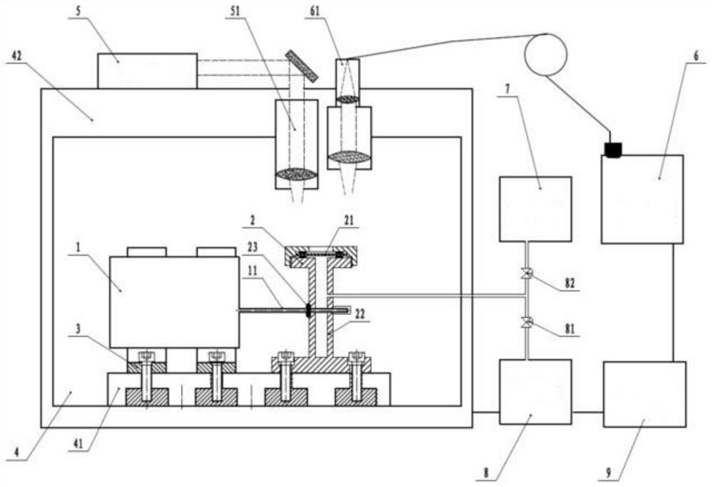
[0043] like figure 1 As shown, in this embodiment, a device for in-situ laser drilling, sampling and sealing of small tubes is specifically provided, aiming to realize the technical integration of laser drilling, sampling and sealing through this device, the device includes:

[0044] ①Sampling container

[0045] The inside of the sampling container 2 is hollow and the inside is a sealed inner cavity. In this embodiment, the sampling container 2 includes: a container cylinder 22, a container cover adapted to the container cylinder 22, and the container cylinder 22 The side wall of the side wall is provided with an insertion hole 23 that is tightly fitted with the sampling tube 11. When the sampling tube 11 is inserted into the insertion hole 23, there should be good sealing between the sampling tube 11 and the wall of the insertion hole 23, and the container cylinder The side wall of the body 22 is provided with an accommodating cavity opposite to the insertion hole 23, so as ...

Embodiment 2

[0063] In this embodiment, a method for in-situ laser drilling, sampling and sealing of small tubes is also provided. This method is applied to the device for in-situ laser drilling, sampling and sealing of small tubes described in Example 1 above. In an embodiment, the specification of the sampling tube 11 is Φ3mmx1mm, and its material is austenitic stainless steel. The method includes:

[0064] S1: degreasing the outer wall of the sampling tube 11 and the inner wall of the sampling container 2, in this embodiment, acet(butyl) ketone degreasing the outer wall of the metal sampling tube 11 and the inner wall of the sampling container 2, and then use Wipe with alcohol to remove surface moisture, and dry with hot air;

[0065] S2: Insert the sampling tube 11 into the body of the sampling container 2 and seal the assembly of the sampling tube 11 and the sampling container 2, and fix the product 1 with the sampling tube 11 and the sampling container 2 on the workbench 4 through th...

Embodiment 3

[0071] In this embodiment, another method for in-situ laser drilling, sampling and sealing of small tubes is provided. This method is applied to the device for in-situ laser drilling, sampling and sealing of small tubes described in Example 1 above. In this embodiment, the specification of the sampling tube 11 is Φ4mmx1.2mm, and the material is austenitic stainless steel. The method includes:

[0072] S1: degreasing the outer wall of the sampling tube 11 and the inner wall of the sampling container 2, in this embodiment, acet(butyl) ketone degreasing the outer wall of the metal sampling tube 11 and the inner wall of the sampling container 2, and then use Wipe with alcohol to remove surface moisture, and dry with hot air;

[0073]S2: Insert the sampling tube 11 into the body of the sampling container 2 and seal the assembly of the sampling tube 11 and the sampling container 2, and fix the product 1 with the sampling tube 11 and the sampling container 2 on the workbench 4 throug...


PUM

PropertyMeasurementUnit
Thicknessaaaaaaaaaa

Abstract

The invention discloses a device and method for in-situ laser drilling sampling and solder sealing of a small pipe, and belongs to the technical field of ultrafast laser drilling and quasi-continuous laser welding methods. Firstly, a laser machining part is installed on a special workbench, the part needing laser drilling is placed in a sampling container, and interface sealing is achieved; vacuumizing is carried out on the sampling container, a sampling valve is closed after the vacuum reaches 10<-3>Pa, and micropores penetrating through the wall thickness of a sampling pipe is machined at a specified part through a picosecond laser; then the atmosphere in the interior of a product is slowly released into the sampling container through a micropore channel; and after the internal air pressure of the product is balanced with the air pressure of the sampling container, a solder sealing laser head is moved to the micropore, and solder sealing is carried out on the micropore in a long-pulse laser welding mode. Laser in-situ near-lossless punching and solder sealing of the sampling pipe in a narrow space are met, near-lossless sampling is carried out on the atmosphere in the interior of a sealed container, and the use performance of a sealed container product is not affected.

Description

technical field [0001] The invention belongs to the technical field of ultrafast laser drilling and quasi-continuous laser welding methods, and in particular relates to a device and method for in-situ laser drilling, sampling and welding of small tubes. Background technique [0002] In recent years, laser technology has developed rapidly, and has been widely used in industrial sectors, and output modes such as ultrafast, quasi-continuous and continuous lasers have been developed. Ultrafast lasers are mainly used for micro-nano processing and precision drilling. Due to the characteristics of short pulses, high peak power and high repetition frequency, ultrafast lasers have high processing precision, extremely small heat-affected zone and are suitable for processing various materials. It is one of the hot spots in laser processing research. Among them, quasi-continuous and continuous lasers have the characteristics of long output time and high average power, and are widely us...

Claims


Application Information

Patent Timeline
IPC IPC(8): B23K26/21B23K26/382B23K26/70
CPCB23K26/382B23K26/21B23K26/70
Inventor 李盛和罗文华郭兴根罗学建李明伟邓辉程亮吕学超窦作勇何建军许崇林
Owner MATERIAL INST OF CHINA ACADEMY OF ENG PHYSICS
Learn More