Method and apparatus for cutting transparent brittle material

A technology for brittle materials and cutting devices, applied in welding/welding/cutting items, laser welding equipment, manufacturing tools, etc., can solve the problems of short depth of focus, low spot energy density, and large volume of linear motors, etc., to achieve long depth of focus, The effect of high energy density

Inactive Publication Date: 2021-04-30
WUHAN HGLASER ENG CO LTD
View PDF14 Cites 1 Cited by
  • Summary
  • Abstract
  • Description
  • Claims
  • Application Information

AI Technical Summary

Problems solved by technology

However, in high-demand cutting, the laser light is usually a high-frequency signal. In order to match its frequency, the requirements for linear motors are usually very high. For example, the motor needs to precisely control the laser pulse in conjunction with the cutting track. It is also necessary to match the frequency of the laser output, usually due to the hardware limitation of the linear motor, and cannot meet the high-precision process cutting requirements, and the cutting efficiency is not high; secondly, the linear motor is usually large in size, and the structural layout and cost of use need to be considered when using it question
[0003] At the same time, in the prior art, there has been a two-dimensional motion of laser scanning formed by a vibrating mirror + a scanning field mirror to achieve material cutting, such as CN107030390A-a solar cell cutting device, which mainly uses a scanning field mirror to focus Laser energy, scanning cutting, but this laser cutting method is removal cutting, which needs repeated cutting many times, layer by layer removal can achieve the predetermined thickness of cutting, and its spot energy density is low, cutting line width, focus Deep and short, unable to focus on the inside of the material, not suitable for cutting transparent and brittle materials such as glass

Method used


Image

  • Method and apparatus for cutting transparent brittle material
  • Method and apparatus for cutting transparent brittle material
  • Method and apparatus for cutting transparent brittle material

Examples


Embodiment 1

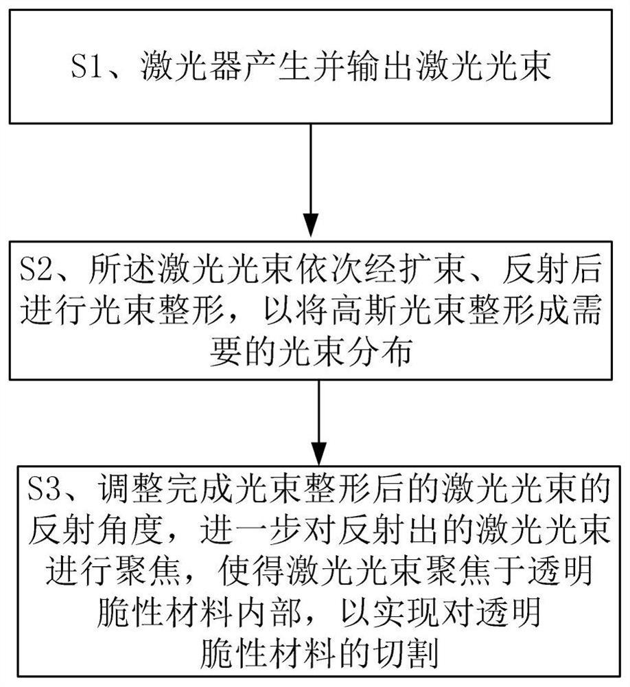
[0038] Such as figure 1 As shown, the present embodiment provides a method for cutting transparent and brittle materials, which includes the following steps:

[0039] S1. The laser generates and outputs a laser beam;

[0040] S2. The laser beam is sequentially expanded and reflected to perform beam shaping, so as to shape the Gaussian beam into a required beam distribution, so as to meet the cutting requirements of different transparent and brittle materials; in this embodiment, the transparent and brittle materials include or Sapphire, etc., the beam shaping can be realized by one or more of beam shaping systems such as conical mirrors, DOE (Difractive Optical Element, diffractive optical elements), spatial modulators, etc.;

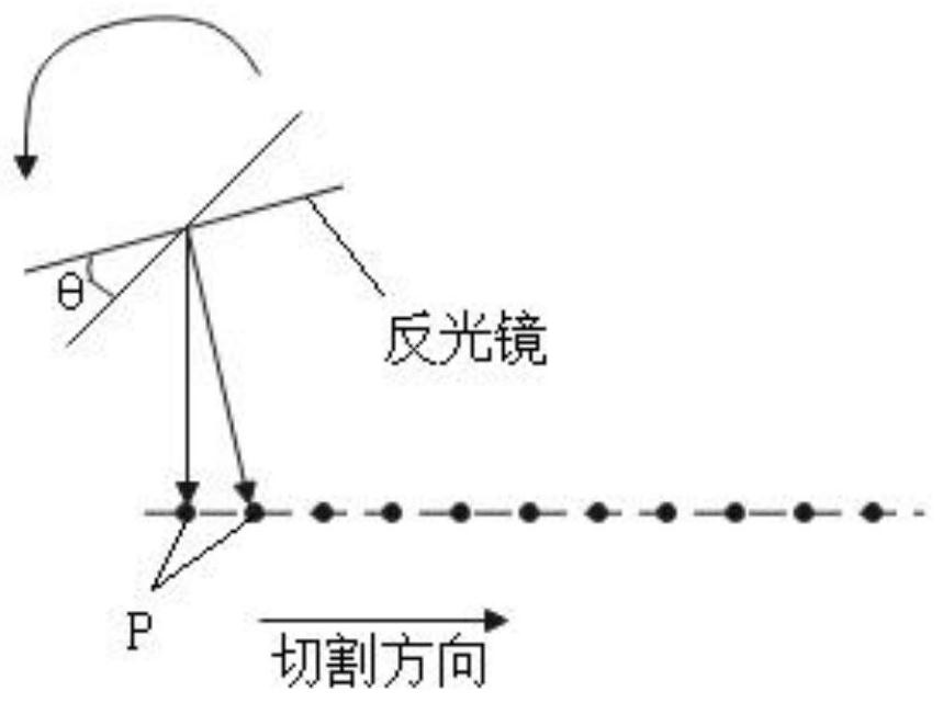
[0041] S3. Adjust the reflection angle of the laser beam after beam shaping, and further focus the reflected laser beam, so that the laser beam is focused inside the transparent and brittle material, so as to realize the cutting of the transparent and ...

Embodiment 2

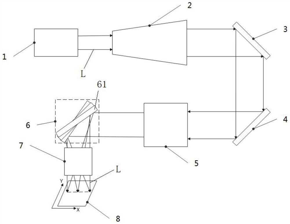
[0048] This embodiment provides a transparent brittle material cutting device for realizing the method described in Embodiment 1, such as image 3 shown, which includes:

[0049] a laser 1, which is used to generate and output a laser beam L;

[0050] Beam expander 2, which is used to adjust the laser spot size and divergence angle;

[0051]Mirror group, beam shaping system 5, the mirror group is used to reflect the laser beam L after the beam expander 2 beam expansion to the beam shaping system 5, so that the Gaussian beam is shaped into the desired shape by the beam shaping system 5 Beam distribution to meet the cutting requirements of different transparent and brittle materials 8; in this embodiment, the transparent and brittle materials 8 include glass or sapphire, and the beam shaping system 5 includes conical mirrors, DOE (Difractive Optical Element, diffractive optical element ), one or more of spatial modulators, etc.;

[0052] A high-speed scanning system 6, which ...

Embodiment 3

[0060] The only difference between this embodiment and Embodiment 2 is that the transparent and brittle material cutting device in this embodiment also includes:

[0061] The Z-direction lifting device is used to drive the transparent and brittle material 8 to move in the Z direction, so as to adjust the position of the focal plane.

[0062] The transparent and brittle material cutting device of this embodiment can adjust the laser beam distribution and focal depth by adjusting the distance between the beam shaping system 5 and the focusing system 7, and adapt different powers according to the light output frequency of the laser, combined with the deflection angle of the mirror The scanning speed and accuracy can be adjusted by controlling the scanning speed, so as to meet the cutting process requirements of different transparent and brittle materials.

[0063] In summary, the present invention is specifically applicable to the cutting of transparent and brittle materials such...


PUM

PropertyMeasurementUnit
diameteraaaaaaaaaa
thicknessaaaaaaaaaa

Abstract

The invention relates to a device and method for cutting a transparent brittle material. The method comprises the following steps that S1, a laser generates and outputs a laser beam; S2, beam shaping is carried out on the laser beam after the laser beam is expanded and reflected in sequence; and S3, the reflection angle of the laser beam after beam shaping is adjusted, and the reflected laser beam is focused, so that the laser beam is focused in a transparent brittle material, and cutting of the transparent brittle material is achieved. Through beam shaping, reflection angle adjustment and focusing of the laser beam, scanning type cutting of the transparent brittle material with a preset thickness can be achieved, and the performance requirement and the use cost of a laser light source are reduced while the machining efficiency is greatly improved.

Description

technical field [0001] The invention relates to the field of optical material processing, in particular to a method and device for cutting transparent and brittle materials. Background technique [0002] At present, the processing of transparent and brittle materials can be realized in many ways, such as using a linear motor with a laser cutting head to cut according to predetermined graphic requirements. In this processing method, the light output signal of the laser needs to cooperate with the moving speed of the linear motor to achieve efficient processing. However, in high-demand cutting, the laser light is usually a high-frequency signal. In order to match its frequency, the requirements for linear motors are usually very high. For example, the motor needs to precisely control the laser pulse in conjunction with the cutting track. It is also necessary to match the frequency of the laser output, usually due to the hardware limitation of the linear motor, and cannot meet...

Claims


Application Information

Patent Timeline
Patent Type & Authority Applications(China)
IPC IPC(8): B23K26/38B23K26/402B23K26/064
CPCB23K26/38B23K26/402B23K26/064B23K26/0643B23K2103/50B23K2103/54
Inventor 王雪辉成迎虹温彬李曾卓王建刚
Owner WUHAN HGLASER ENG CO LTD
Why Eureka
Try Eureka