A circuit for triggering an excimer laser to generate plasma
An excimer laser and plasma technology, which is applied to lasers, phonon exciters, laser parts, etc., can solve the problem of reducing the performance of excimer lasers, the high-voltage pulse signal does not have a fast frontier, and the time synchronization of excimer lasers cannot be achieved. and other problems to achieve the effect of reducing signal jitter, removing noise interference, and reducing jitter
- Summary
- Abstract
- Description
- Claims
- Application Information
AI Technical Summary
Problems solved by technology
Method used
Image
Examples
Embodiment 1
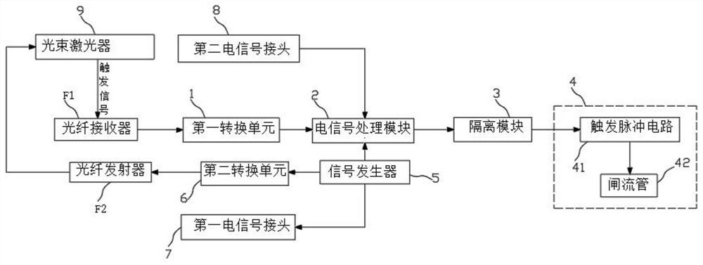
[0057] A device for triggering an excimer laser, which comprises the following components:
[0058] Signal acquisition module for collecting the trigger signal of the beam laser 9 that sends seed light to the gas laser 4;
[0059]Electrical signal processing module 2, for receiving and processing the trigger signal of the beam laser 9 collected by the signal acquisition module, and the processed trigger signal is input to the enable end of the gas laser 4, so that the time for the seed light to reach the gas laser 4 is synchronized with the discharge time of the gas laser 4; the discharge time of the gas laser 4 is controlled by the enable end of the gas laser 4.
[0060] The signal acquisition module comprises a fiber optic receiver F1 and a first conversion unit 1; the trigger signal of the beam laser 9 is input to the photoresistor of the optical fiber receiver F1 in the form of an optical signal; the output terminal of the optical fiber receiver F1 is electrically connected t...
Embodiment 2
[0078] In the basic line of Example 1, the following are described separately:
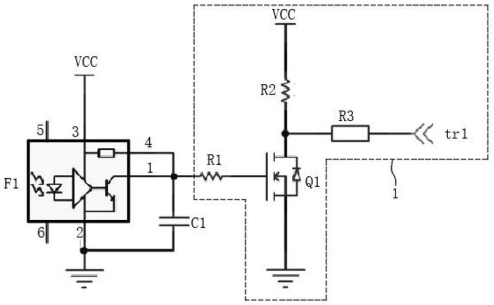
[0079] as Figure 1 and Figure 2 As shown, the signal acquisition module comprises a fiber optic receiver F1 of model R2526 and a first conversion unit 1. The first conversion unit 1 includes a first FET Q1, a first resistor R1, a second resistor R2, a third resistor R3. The output of the fiber optic receiver F1 is connected to the gate of the first FET Q1, the drain of the first FET Q1 is connected to the 5V DC voltage through the second resistor R2, and the source of the first FET Q1 is grounded. The drain of the first FET Q1 is also connected as the output to the input of the electrical signal processing module 2 through the third resistor R3, the fiber optic receiver F1 is used as the pin 1 of the output terminal through the gate of the first resistor R1 and the first FET Q1, pin 1 of the fiber optic receiver F1 is also connected to pin 4, and the first capacitor C1 is connected between pin 1 and ...
Embodiment 3
[0085]On the basis of Examples 1 and 2, the first conversion unit 1, optical fiber receiver F1, the second electrical signal connector 8 is removed from Example 2, and the following components are added:
[0086] Signal generator 5 for outputting a signal that coincides with the trigger signal of the beam laser 9;
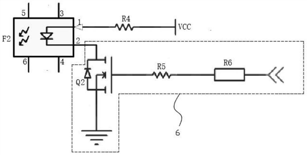
[0087] Second conversion unit 6 for outputting potentials that are different from the potential at the output of signal generator 5;
[0088] Fiber optic transmitter F2, for converting the potential output of the second conversion unit 6 into an optical signal, which is transmitted to the beam laser 9 for triggering the beam laser 9 to generate seed light.
[0089] The first output of the signal generator 5 is connected to the 555 timer F3 in the electrical signal processing module 2 as the input pin 6 and pin 2, the second output of the signal generator 5 is connected to the input terminal of the second conversion unit 6; the output of the second conversion unit 6 is...
PUM
 Abstract
Description
Claims
Application Information
 - R&D
- Intellectual Property
- Life Sciences
- Materials
- Tech Scout
- Unparalleled Data Quality
- Higher Quality Content
- 60% Fewer Hallucinations
Browse by: Latest US Patents, China's latest patents, Technical Efficacy Thesaurus, Application Domain, Technology Topic, Popular Technical Reports.
© 2025 PatSnap. All rights reserved.Legal|Privacy policy|Modern Slavery Act Transparency Statement|Sitemap|About US| Contact US: help@patsnap.com


