Dielectric filter with mixed dielectric resonator
A technology of dielectric filter and mixed medium, which is applied in the direction of waveguide devices, electrical components, circuits, etc., and can solve the problems affecting the transmission power and energy consumption of the transmitter, affecting the noise figure of the receiver system, and the large insertion loss of the dielectric filter. , to achieve the effect of improving no-load quality factor, low cost and low loss performance
- Summary
- Abstract
- Description
- Claims
- Application Information
AI Technical Summary
Problems solved by technology
Method used
Image
Examples
Embodiment 1
[0029] With the rapid development of wireless technologies such as new-generation mobile communications, satellite communications, Internet of Things, and new-generation integrated radar systems, the overall communication equipment is moving toward miniaturization, high density, low cost, high performance, low latency, and low power consumption. Rapid development. Since the dielectric filter is filled with a medium with a high dielectric constant, it is conducive to miniaturization; at the same time, the production process is mature and low cost can be achieved. Dielectric filters conform to the development trend of current communication systems and have a large number of engineering application requirements. However, the existing dielectric filter has a large insertion loss problem, which leads to high overall power consumption in the use of base stations, satellites, and radar systems. Large-scale use has a great impact. In view of the above problems, the present invention...
Embodiment 2
[0035] The overall composition of the dielectric filter containing the mixed-medium resonator is the same as that of Embodiment 1. The present invention can change the resonator by setting a debugging blind hole above all resonant cavities of the body, including non-mixed-medium resonant cavities and mixed-medium resonant cavities. the resonant frequency.
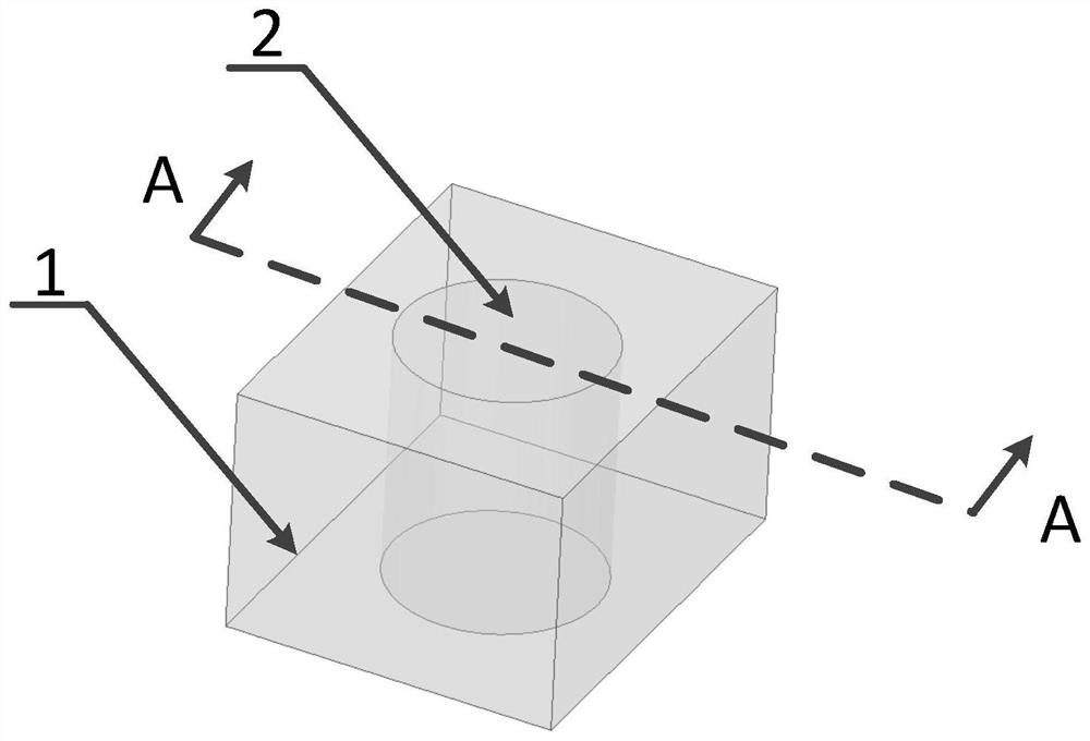
[0036] In this embodiment, in order to clearly illustrate the structure of the dielectric resonator composed of two different media of the present invention, see Figure 5 , Figure 5 It is a perspective view of a dielectric resonator with a tuning blind hole provided by two kinds of media with different dielectric constants provided in the present invention. The resonator is composed of a cylindrical dielectric block 2 and a debugging blind hole arranged above 3 and the medium 1 of the rectangular parallelepiped space around the dielectric block 2, the dielectric block 2 and the body space 1 around the dielectric block 2 ...
Embodiment 3
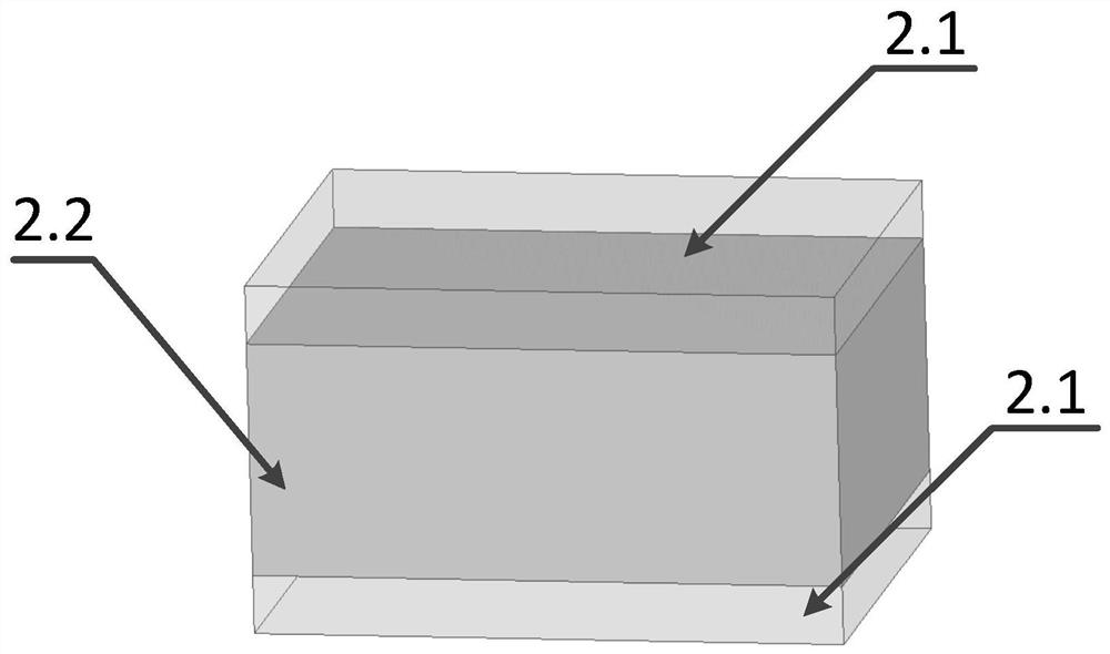
[0040] The overall composition of the dielectric filter containing the mixed-dielectric resonator is the same as that of Embodiment 1-2. The dielectric block in the mixed-dielectric resonator of the present invention is composed of two or more than two kinds of media with different dielectric constants. In the present invention Combination of two media or wrapped state, see figure 2 ; or in stacked state, see figure 1 .
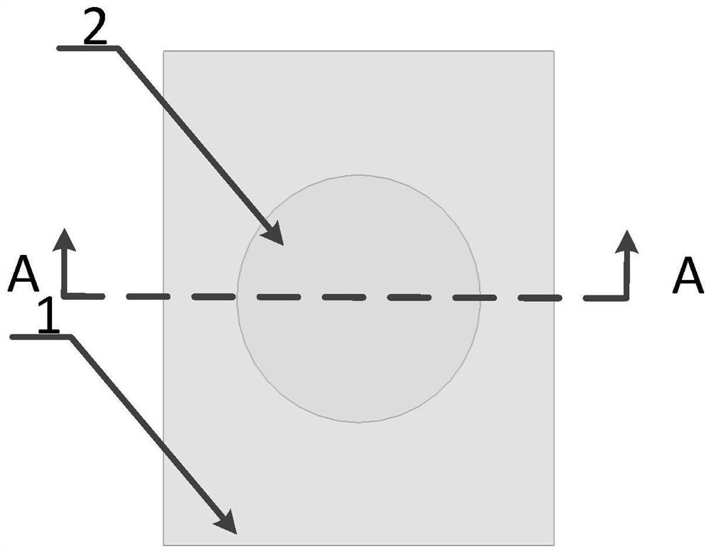
[0041] In this embodiment, for the wrapping state of the media combination, see figure 2 , figure 2 A side view of a dielectric resonator composed of two kinds of media with different dielectric constants provided for the present invention, the resonator is composed of a cylindrical dielectric block 2, a debugging blind hole 3 arranged above and a rectangular parallelepiped around the dielectric block 2 Composed of space 1, the outer cuboid space 1 of the dielectric block 2 and the dielectric block 2 are two kinds of media with different dielectric cons...
PUM
 Abstract
Description
Claims
Application Information
 - R&D
- Intellectual Property
- Life Sciences
- Materials
- Tech Scout
- Unparalleled Data Quality
- Higher Quality Content
- 60% Fewer Hallucinations
Browse by: Latest US Patents, China's latest patents, Technical Efficacy Thesaurus, Application Domain, Technology Topic, Popular Technical Reports.
© 2025 PatSnap. All rights reserved.Legal|Privacy policy|Modern Slavery Act Transparency Statement|Sitemap|About US| Contact US: help@patsnap.com


