Subsurface coupled wetland for nitrogen and phosphorus removal

A technology for denitrification, phosphorus removal and wetlands, applied in the field of water treatment, can solve problems such as affecting the treatment effect, affecting the water flow path, and blocking the substrate, and achieves the effect of high pollutant removal capacity, alleviation of blockage, and improvement of service life.

Inactive Publication Date: 2021-05-28
HANGZHOU QINLIN ECOLOGICAL TECH CO LTD
View PDF5 Cites 1 Cited by
  • Summary
  • Abstract
  • Description
  • Claims
  • Application Information

AI Technical Summary

Problems solved by technology

In the surface flow artificial wetland, the sewage flows through the surface of the wetland at a relatively slow speed, which has the advantages of less investment, simple operation, and low operating cost, but the disadvantages are that it occupies a large area, and the pollutant load and hydraulic load rate are small. Pollution capacity is limited
In some areas in the north, due to the cold airflow in winter, the surface is prone to icing, which affects the treatment effect
[0004] The characteristic of the subsurface constructed wetland is that the sewage seeps under the surface of the wetland filler, so it can make full use of the biofilm on the surface of the filler and the plant roots and other functions to treat the wastewater, and the sanitary conditions are good, and the treatment effect is less affected by the climate; the subsurface flow The key point and difficulty in the design of constructed wetlands is its water inlet and distribution system, that is, the limited sewage needs to be evenly distributed on the surface of a large-area filter bed, and its design and calculation are difficult; at the same time, subsurface flow constructed wetlands are prone to clogging after a period of use
Blockage will deteriorate the hydraulic performance of the wetland, thereby affecting the water flow path, and ultimately affect the treatment effect and operating life of the wetland. In addition, due to blockage, water will accumulate on the surface of the filler, making it easier for mosquitoes and flies to breed, thereby deteriorating the sanitary environment
[0005] At the same time, because the existing surface flow constructed wetland / subsurface flow constructed wetland does not have a uniform water distribution structure, a large amount of water will appear when the wetland is in a state of hydraulic overload for a long time, resulting in matrix blockage

Method used


Image

  • Subsurface coupled wetland for nitrogen and phosphorus removal
  • Subsurface coupled wetland for nitrogen and phosphorus removal
  • Subsurface coupled wetland for nitrogen and phosphorus removal

Examples


Embodiment 1

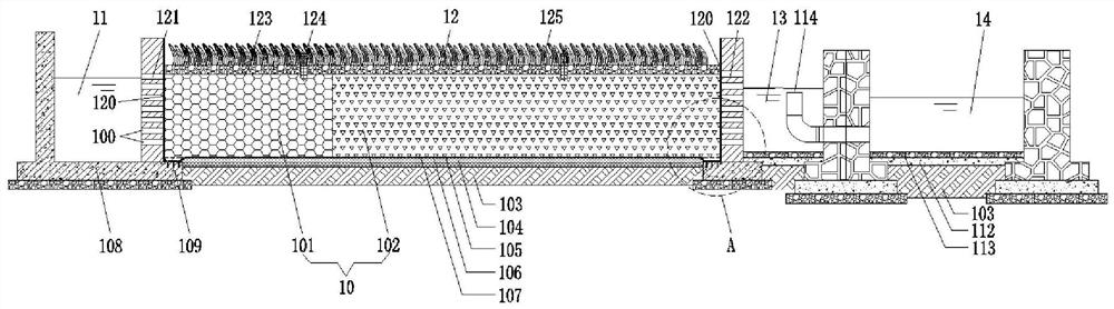
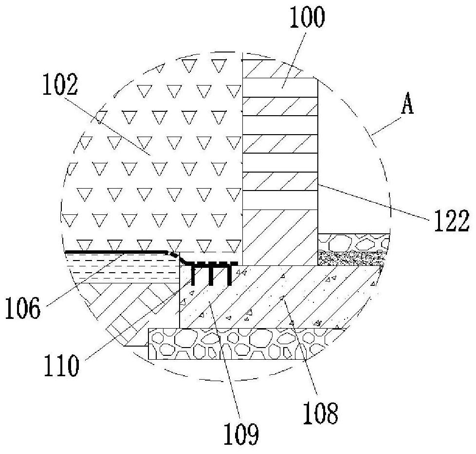
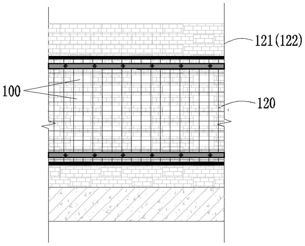
[0040] Such as Figure 1-5As shown, this embodiment discloses a subsurface-surface coupled wetland for denitrification and phosphorus removal, including an inlet channel 11 , a wetland main body 12 , an outlet channel 13 and a water level adjustment pool 14 arranged in sequence along the water inlet direction. The wetland main body 12 includes an inlet water distribution flower wall 121, an outlet water distribution flower wall 122, and a filling area between the inlet water distribution flower wall 121 and the outlet water distribution flower wall 122, and the filling area is filled with phosphorus removal filter material. The water inlet distribution flower wall 121 is arranged at the junction of the water inlet channel 11 and the wetland body 12 , and the outlet water distribution flower wall 122 is arranged at the junction of the wetland body 12 and the outlet channel 13 . The water inlet distribution wall 121 and the outlet water distribution wall 122 are respectively fix...

Embodiment 2

[0048] Such as Image 6 As shown, this embodiment discloses a subsurface-surface coupled wetland for denitrification and phosphorus removal. The difference between this embodiment and Embodiment 1 is only that the front end of the release type filter area 101 and the front end of the filter type filter area 102 The rear ends are respectively provided with pebble filling areas 114 . The rest of the structure of this embodiment is the same as that of Embodiment 1. In this embodiment, by setting the pebble filling area 114 and using it together with the water distribution flower wall, the effect of uniform water distribution can be better realized, and the rest of the effects of this embodiment are the same as those of Embodiment 1.


PUM


Abstract

The invention discloses a subsurface coupled wetland for nitrogen and phosphorus removal. The subsurface coupled wetland comprises a water inlet channel, a wetland main body and a water outlet channel which are sequentially arranged along a water inlet direction, wherein the wetland main body comprises a water inlet distribution lattice wall, a water outlet distribution lattice wall and a filler area arranged between the water inlet distribution lattice wall and the water outlet distribution lattice wall, the filler area is filled with a phosphorus removal filter material, the water inlet distribution lattice wall is arranged at the joint of the water inlet channel and the wetland main body, the water outlet distribution lattice wall is arranged at the joint of the wetland main body and the water outlet channel, and the water inlet distribution lattice wall and the water outlet distribution lattice wall are respectively provided with a plurality of rows of water through holes. According to the invention, the subsurface coupled wetland is used for river channel water quality treatment, shows horizontal subsurface flow at low flow, has good pollutant removal capacity, ensures effluent quality, takes surface flow as a main part and subsurface flow as an auxiliary part at high flow, prevents suspended matters from entering a filter bed to cause blockage, and prolongs the service life of a wetland; and the water distribution lattice walls are respectively arranged at the water inlet end and the water outlet end of the wetland main body, so that self-regulation of flow is realized, surface flow / subsurface flow can be automatically regulated according to the water level, and manual control regulation is not needed.

Description

technical field [0001] The invention relates to the technical field of water treatment, in particular to a subsurface-surface coupled wetland for nitrogen and phosphorus removal. Background technique [0002] The pollution of river water has the following characteristics: high concentration of nitrogen and phosphorus and low concentration of suspended solids in dry season; high concentration of suspended solids and low concentration of nitrogen and phosphorus in rainy season. The ideal technology for controlling river water pollution should adapt to the characteristics of this pollution, effectively remove nitrogen and phosphorus in the water during the dry season, and reduce the damage caused by suspended solids to the treatment facilities during the rainy season. The overall requirements should be to treat both symptoms and root causes, be efficient and safe , low cost, and sustainable, can establish the decontamination and self-purification ability of the river water body...

Claims


Application Information

Patent Timeline
Patent Type & Authority Applications(China)
IPC IPC(8): C02F9/14C02F3/32C02F3/30C02F1/28C02F101/10C02F101/16
CPCC02F9/00C02F3/327C02F3/302C02F1/001C02F1/281C02F2101/105C02F2101/16C02F2301/08
Inventor 杨伟煜王光荣刘丹迪周锋余艺鑫
Owner HANGZHOU QINLIN ECOLOGICAL TECH CO LTD
Why Eureka
Try Eureka