Eureka AIR delivers breakthrough ideas for toughest innovation challenges, trusted by R&D personnel around the world.

A method for encapsulating flat membrane elements used in membrane aerated biofilm reactors

A technology of membrane aeration biofilm and encapsulation method, which is applied in the field of encapsulation of flat membrane elements, can solve the problems of unsuitable sealing, low adhesive strength, and poor adhesion, and achieve the effect of ensuring integrity

Active Publication Date: 2021-10-29
NANJING FORESTRY UNIV
View PDF1 Cites 0 Cited by
  • Summary
  • Abstract
  • Description
  • Claims
  • Application Information

AI Technical Summary

Problems solved by technology

Although this method can quickly and reliably fix the membrane on the frame, this packaging method is not suitable for the packaging of flat membrane elements in membrane aerated biofilm reactors in terms of sealing, because the silicone rubber membrane used for membrane aeration It is a dense and non-porous thin membrane material with good gas transmission performance. The use of ultrasonic welding will damage the membrane material itself, and the purpose of membrane aeration cannot be achieved; the patent CN 210825659 U adopts the method of gluing and bonding to package the bubble-free aeration The gas plate membrane element, through the liquid silicone rubber, glues the silicone rubber membrane material on both sides of the support frame to realize the bonding of the two
This method can realize the integrity of the silicone rubber membrane after encapsulation, but the adhesiveness between the membrane material and the supporting frame is poor, and the adhesive strength and durability will change with the chemical properties of the adhesive and the use conditions. The risk of the sheet falling off the support frame is suitable for operation under a slight pressure with an aeration pressure of 0.1-0.5kPa, and the bonding strength is not high, so it is limited in use
[0004] It can be seen that the current packaging method of flat membrane elements has the following problems: (1) hot-melt welding cannot guarantee the integrity of the aeration membrane; (2) the bonding strength between the membrane and the supporting frame is not high, and the exposure The air pressure is low; (3) The bubble-free aerated flat membrane element does not take into account the water accumulation in the membrane cavity that may occur in practical applications; (4) The packaging method of the bubble-free aerated flat membrane element only starts from the package Considered from the perspective of the membrane aerated biofilm reactor, without considering its stability as the biofilm carrier of the membrane aerated biofilm reactor; (5) The expansion volume of the non-bubble aerated flat membrane element changes significantly during aeration, and the membrane ratio of the reactor in actual application The surface area is limited and it is not conducive to providing stable carrier conditions for microbial attachment and growth
[0005] The current packaging method of flat membrane elements is not suitable for the long-term stable operation of membrane aerated biofilm reactors in terms of packaging methods, element structures, operating conditions and application requirements.

Method used


Image

  • A method for encapsulating flat membrane elements used in membrane aerated biofilm reactors
  • A method for encapsulating flat membrane elements used in membrane aerated biofilm reactors
  • A method for encapsulating flat membrane elements used in membrane aerated biofilm reactors

Examples


Embodiment 1

[0047] Prepare a pair of frames including the support frame and the beam in the frame. The beam in the frame has no slope. Reserve semi-circular grooves at the support frame and the beam in the frame, so that they can be aligned and spliced ​​to form air inlets and drains. and through holes. Apply a uniform layer of encapsulant on the grooved side of the frame (A1:B1 is 1:0.6 by volume), and cut a silicone rubber film with a thickness of 100 μm to a size slightly larger than the frame, paste it on the coated On the surface of one side of the frame of the encapsulant, apply a slight force to make the silicone rubber film adhere to the frame, and naturally cure in the air for 8 hours at room temperature.

[0048] Take a frame with a silicone rubber film that has been cured in the above steps, and evenly coat the encapsulant two (A2:B2 with a volume ratio of 1:1) on the frame with the silicone rubber film on the other side of the silicone rubber film. around the side, and place ...

Embodiment 2

[0053] Prepare a pair of frames including the support frame and the beam in the frame. The beam in the frame has no slope. Reserve semi-circular grooves at the support frame and the beam in the frame, so that they can be aligned and spliced ​​to form air inlets and drains. and through holes. Apply a uniform layer of encapsulant on the grooved side of the frame (A1:B1 is 1:0.6 by volume), and cut a silicone rubber film with a thickness of 100 μm to a size slightly larger than the frame, paste it on the coated On the surface of one side of the frame of the encapsulant, apply a slight force to make the silicone rubber film adhere to the frame, and naturally cure in the air for 8 hours at room temperature.

[0054] Take a frame with a silicone rubber film that has been cured in the above steps, and evenly coat the encapsulant two (A2:B2 is 1:1 by volume) on the frame with the silicone rubber film on the other side of the silicone rubber film. around the side, and place a silicone...

Embodiment 3

[0060] The difference from Example 2 is that the semi-finished product of the flat membrane element is covered with a non-woven fabric (specification is 30g / m2). 2 ) is hydrophobic, covered and pasted on the two sides of the semi-finished flat membrane element, and cured in the air for 8 hours at room temperature to complete the encapsulation of the flat membrane element.

[0061] The packaged flat membrane element is 15cm long, 7cm wide and 0.8cm thick, and the effective membrane surface area is 162cm 2 . The flat membrane element was vertically placed and fixed in a cylindrical reactor with a height of 22 cm and a diameter of 8 cm along the length direction. At a water temperature of 25°C, the specific surface area of ​​the membrane is 16.2m 2 / m 3 , using an air compressor to supply air, the aeration pressure of the flat membrane element is 3kPa, 4kPa and 6kPa respectively, and under the condition of no hydraulic disturbance, according to the urban construction industry ...


PUM

PropertyMeasurementUnit
widthaaaaaaaaaa
thicknessaaaaaaaaaa
diameteraaaaaaaaaa

Abstract

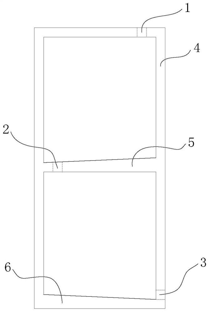
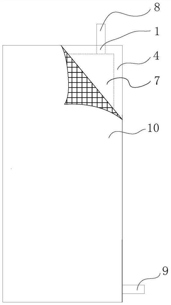
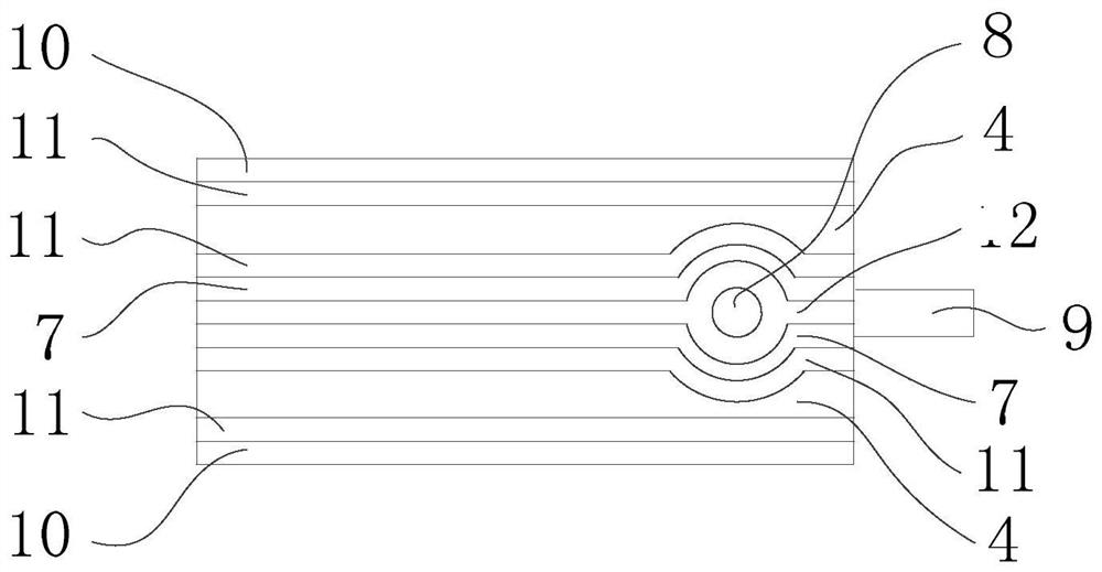
The invention discloses a method for encapsulating a flat membrane element of a membrane aerated biofilm reactor. Two pieces of silicon rubber membranes are glued together by encapsulation glue to form a closed membrane cavity, and are encapsulated by a pair of supporting frames. The glue is clamped for stability and protection; the non-woven fabric is pasted on the outside of the support frame through the packaging glue; the air inlet and the drain are reserved on the support frame, the air inlet is connected to the air intake pipe, and the drain is connected to the drain pipe; There is a through hole on the inner beam; when working, the compressed air enters the membrane cavity through the inlet pipe through the inlet, and diffuses to the entire membrane cavity through the through hole on the inner beam with a slope, and the accumulated water in the membrane cavity passes through the through hole The holes and the drains on the sloped bottom edge of the support frame drain periodically through drains. The method can ensure the integrity, tightness and bonding strength of the membrane cavity, form a stable and reliable membrane aeration cavity of the flat membrane element, and facilitate the growth of biofilm, so that the flat membrane element has long-term stable working performance.

Description

technical field [0001] The application belongs to the field of environmental engineering, relates to a gas membrane separation technology for water treatment, and in particular relates to a packaging method for a flat membrane element used in a membrane aeration biofilm reactor. Background technique [0002] Membrane aeration biofilm reactor (MABR) is a sewage treatment process that combines traditional biofilm method with gas membrane separation technology. It diffuses into the biofilm growing on the surface of the membrane in the form of dissolution and diffusion, which improves the aeration efficiency and oxygen utilization rate while reducing the energy consumption of aeration. advantages, while avoiding secondary pollution. The membrane aeration element not only plays the role of membrane aeration, but also acts as a carrier for the attachment and growth of microorganisms, so the membrane aeration element with stable and reliable quality is the core of the MABR sewage ...

Claims


Application Information

Patent Timeline
Patent Type & Authority Patents(China)
IPC IPC(8): C02F3/20C02F3/12C02F7/00B01D63/08
CPCB01D63/081C02F3/1268C02F3/201C02F7/00C02F2209/03Y02W10/10
Inventor 梅翔张子淼王展杨梦梦沈文天高寒王偲张雷夏冬雨
Owner NANJING FORESTRY UNIV
Why Eureka
Eureka Blog
Learn More