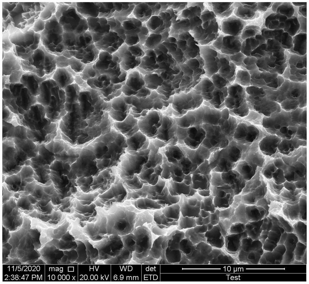
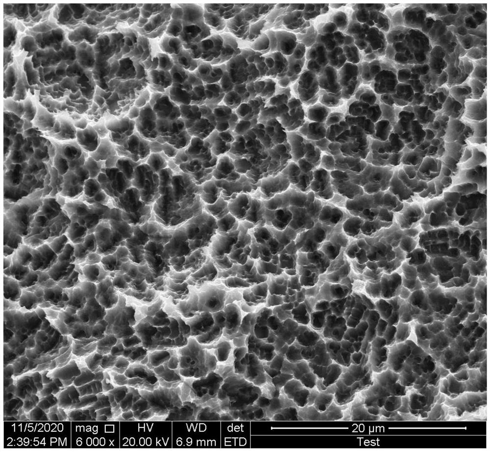
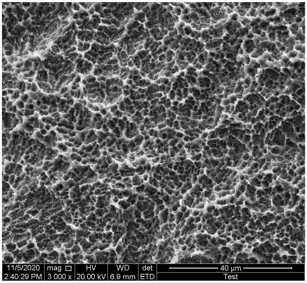
A surface treatment process for 3D printed implants

A 3D printing and surface treatment technology, applied in the direction of surface reaction electrolytic coating, dental implants, additive processing, etc., can solve the problem of decreased osseointegration and mechanical properties of oral implants, uncontrollable pore structure and pore size, and deep holes. Unable to completely remove impurities and other problems, to achieve the effect of increasing ion exchange speed, suppressing stress shielding, and increasing stability

Active Publication Date: 2021-10-22
JIANGSU TRAUSIM MEDICAL INSTR
View PDF10 Cites 0 Cited by
  • Summary
  • Abstract
  • Description
  • Claims
  • Application Information

AI Technical Summary

Problems solved by technology

Most of the commercial oral implants on the market are solid bodies. Although they have good biocompatibility, they still have their own problems: the osseointegration performance of solid oral implants is not high and the elastic modulus is significant. It is higher than the surrounding bone tissue, forming a "stress shielding" effect, leading to the absorption of surrounding bone tissue, which restricts its extensive clinical application
In the prior art, the foaming method is used to make oral implants with a porous structure, that is, a foaming agent is added to the manufacturing material, and the bubbles generated by the reaction of the foaming agent are used to form the porous structure in the oral implant, but this There are technical problems in the method that the pore structure and pore size cannot be controlled. Unreasonable pore size and pore structure will lead to a decline in the osseointegration and mechanical properties of oral implants, which is difficult to meet the clinical needs of oral cavity
[0004] In addition, the hydrophilicity of implants is very important for the biocompatibility of dental implants; however, due to its porous structure, deep pores cannot completely remove impurities during surface treatment, so a series of treatments are required Ways to co-process the surface of 3D printed implants

Method used


Image

  • A surface treatment process for 3D printed implants
  • A surface treatment process for 3D printed implants
  • A surface treatment process for 3D printed implants

Examples


Embodiment 1

[0039] A surface treatment process for 3D printing implants, comprising the following steps:

[0040] S1: The printing process of the 3D printed implant: (1) Design the 3D model of the implant with a pore structure; (2) Slice the 3D model, the slice thickness is 28 μm, and plan the scanning path; use the nine-square grid method for partition scanning, and the area size is 2× 2mm, the scanning direction is deflected by a certain angle when scanning different layers, and the deflection angle is set to 37°. (3) Laser selective melting equipment adopts a combination of vacuuming and replacement. Firstly, the vacuum is pumped to 80KPa, and then high-purity Ar gas is filled into the forming chamber. Repeated replacements in this way, the final oxygen content is less than 100ppm, and the pressure is 30mbar. Argon environment; when printing, the substrate is preheated through the preheating function, the preheating temperature is 100°C, after the substrate is preheated, a layer of new...

Embodiment 2

[0044] A surface treatment process for 3D printing implants, comprising the following steps:

[0045] S1: The printing process of the 3D printed implant: (1) Design the 3D model of the implant with a pore structure; (2) Slice the 3D model, the slice thickness is 22 μm, and plan the scanning path; use the nine-square grid method for partition scanning, the area size is 2× 2mm, the scanning direction is deflected by a certain angle when scanning different layers, and the deflection angle is set to 37°. (3) Laser selective melting equipment adopts a combination of vacuuming and replacement. Firstly, the vacuum is pumped to 80KPa, and then high-purity Ar gas is filled into the forming chamber. Repeated replacement in this way, the final oxygen content is less than 100ppm, and the pressure is 18mbar. Argon environment; when printing, the substrate is preheated through the preheating function, and the preheating temperature is 100°C. After the substrate is preheated, a layer of new ...

Embodiment 3

[0049] A surface treatment process for 3D printing implants, comprising the following steps:

[0050] S1: The printing process of 3D printed implants: (1) Design the 3D model of the implant with a pore structure; (2) Slice the 3D model, the slice thickness is 24 μm, and plan the scanning path; use the nine-square grid method for partition scanning, and the area size is 2× 2mm, the scanning direction is deflected by a certain angle when scanning different layers, and the deflection angle is set to 37°. (3) The selective laser melting equipment adopts a combination of vacuuming and replacement. Firstly, the vacuum is pumped to 80KPa, and then high-purity Ar gas is filled into the forming chamber. Repeated replacement in this way, the final oxygen content is less than 100ppm, and the pressure is 32mbar. Argon environment; when printing, the substrate is preheated through the preheating function, and the preheating temperature is 100°C. After the substrate is preheated, a layer of...


PUM

PropertyMeasurementUnit
diameteraaaaaaaaaa
Vickers hardnessaaaaaaaaaa
yield strengthaaaaaaaaaa

Abstract

The invention discloses a surface treatment process of a 3D printing implant. First, the TA1 powder is melted layer by layer by laser selection to obtain the implant; then the implant is sequentially subjected to sandblasting, acid etching, and electropolishing oxidation treatment to obtain 3D printing with high biological safety, excellent osseointegration, and good mechanical properties implant. Beneficial effects: Sandblasting and acid etching can be used to generate primary and secondary nested pits on the surface of the implant, synergistically enhance the attachment, proliferation and differentiation of osteoblasts, and promote osseointegration; Ultrasonic device to promote ion exchange in channels and pits, reduce acid etching treatment time; use perchloric acid-glacial acetic acid electropolishing oxidation process to increase the dissolved oxygen step, increase the oxygen density in the acid solution, combined with the optimization of various parameters Settings, precisely control the surface roughness of the implant, form a thicker oxide film on the surface, and increase hydrophilicity.

Description

technical field [0001] The invention relates to the technical field of implants, in particular to a surface treatment process for 3D printed implants. Background technique [0002] As an artificial tooth root to replace natural tooth root, oral implant has the characteristics of high comfort, high efficiency of mastication recovery and no damage to adjacent teeth. Implantation of oral cavity has become the first choice for clinical restoration of dentition and dentition defect. Most of the commercial oral implants on the market are solid bodies. Although they have good biocompatibility, they still have their own problems: the osseointegration performance of solid oral implants is not high and the elastic modulus is significant. It is higher than the surrounding bone tissue, forming a "stress shielding" effect, leading to the absorption of surrounding bone tissue, which restricts its extensive clinical promotion. [0003] In order to solve the above problems, scholars have d...

Claims


Application Information

Patent Timeline
Patent Type & Authority Patents(China)
IPC IPC(8): B22F10/28B22F10/85B22F10/62B22F10/66B33Y10/00B33Y80/00B33Y70/00B33Y50/02B33Y40/20C23F1/26C25F3/26C25D11/26C23F17/00B24C1/06A61C8/00
CPCA61C8/0087B24C1/06B33Y10/00B33Y50/02B33Y70/00B33Y80/00B33Y40/20C23F1/26C23F17/00C25D11/26C25F3/26
Inventor 尹克云钱晓锦曹云鹏徐骏伟
Owner JIANGSU TRAUSIM MEDICAL INSTR
Why Eureka
Try Eureka