Disk type permanent magnet synchronous motor, energy storage flywheel and method
A technology of permanent magnet synchronous motor and energy storage flywheel, which is applied in the field of energy storage flywheel and disc permanent magnet synchronous motor to achieve the effect of broadening the application range
- Summary
- Abstract
- Description
- Claims
- Application Information
AI Technical Summary
Problems solved by technology
Method used
Image
Examples
Embodiment 1
[0066] This embodiment discloses a new disc-type permanent magnet synchronous motor for energy storage flywheel based on magnetic suspension support. The motor cooperates with the magnetic suspension bearing system that plays a supporting role in the energy storage flywheel to realize the energy exchange of mechanical kinetic energy and electrical energy of the energy storage flywheel .
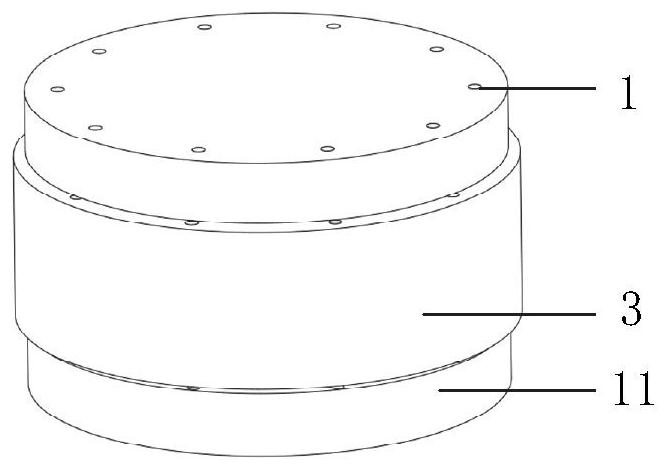
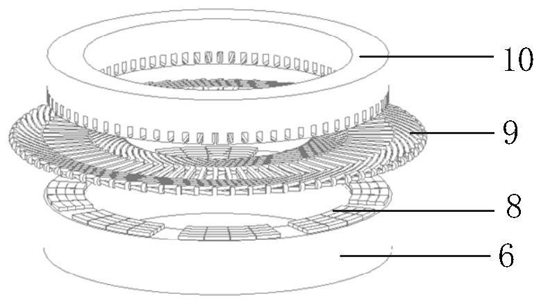
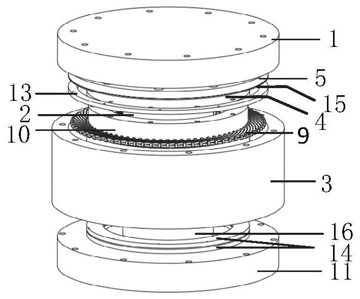
[0067] The implementation example of the present disclosure takes an 8-pole 72-slot disc permanent magnet synchronous motor as an example, figure 1 The overall structure of the energy storage flywheel based on magnetic suspension support proposed by the present invention includes an upper end cover 1, an upper radial magnetic bearing 2, a casing 3, a non-magnetic buckle 4, an upper magnetic disc 5, a rotor yoke 6, Rotating shaft 7, permanent magnet pole 8, armature winding 9, stator core 10, lower end cover 11, flywheel rotor 12, axial protective bearing 13, axial passive magnetic bearing 14,...
Embodiment 2
[0082] The purpose of this embodiment is to provide the installation steps of the disc permanent magnet synchronous motor and the energy storage flywheel: first install the integral flywheel rotor 12 in place, and then determine the stator disc 10 by measuring the axial position of the permanent magnet 8 on the upper end face of the flywheel rotor In order to ensure the axial clearance between the stator disk 10 and the rotor disk of the motor, in addition, the overall rotor needs to be positioned axially by installing a position sensor to ensure that the rotor disk of the motor will not be in the position of the stator disk 10. The suction effect is attached to the stator disk 10 .
Embodiment 3
[0084] The purpose of this embodiment is to provide a working method for a disc permanent magnet synchronous motor, including:
[0085] The air gap mentioned in the main magnetic circuit is the air gap a between the stator core 10 and the rotor disc, adding an additional Figure 11 Specifically describe the main magnetic circuit of the motor, and mark the air gap in the main magnetic circuit at the same time;
[0086] by Figure 11 As an example to illustrate the magnetic circuit of the motor, the permanent magnetic flux passes through the rotor disk permanent magnet 8-1→air gap a→stator tooth 10-11→stator yoke 10-2→adjacent stator tooth 10-12→air gap a→ Adjacent rotor disk permanent magnet 8-2→rotor yoke disk 6→finally return to the original rotor disk permanent magnet 8-1 to form a closed loop;
[0087]Two adjacent permanent magnets in the circumferential direction have opposite polarities. When the prime mover rotor 12 rotates, the permanent magnet poles 8 act as the roto...
PUM
 Abstract
Description
Claims
Application Information
 - R&D
- Intellectual Property
- Life Sciences
- Materials
- Tech Scout
- Unparalleled Data Quality
- Higher Quality Content
- 60% Fewer Hallucinations
Browse by: Latest US Patents, China's latest patents, Technical Efficacy Thesaurus, Application Domain, Technology Topic, Popular Technical Reports.
© 2025 PatSnap. All rights reserved.Legal|Privacy policy|Modern Slavery Act Transparency Statement|Sitemap|About US| Contact US: help@patsnap.com


