
Capacitive deionization unit, device and method

A capacitive deionization and anion technology, applied in the field of desalination of water resources, can solve the problems of increasing desalination capacity and energy consumption

Active Publication Date: 2021-07-30
BEIHANG UNIV
View PDF5 Cites 2 Cited by
  • Summary
  • Abstract
  • Description
  • Claims
  • Application Information

AI Technical Summary

Problems solved by technology

However, some existing technologies introduce an anion exchange membrane on the outside of the anode, and add a cation exchange membrane on the outside of the cathode. The ion exchange membrane blocks the repulsion of the same ion and also inhibits the occurrence of some side reactions. This method greatly improves the Coulomb of the capacitive deionization process. efficiency, thereby increasing the desalination capacity and reducing energy consumption, but there are high membrane internal resistance and contact internal resistance brought by the introduction of self-supporting ion exchange membranes (because independent membranes need to maintain a certain mechanical strength and self-supporting properties, ion exchange The increase in the amount of polymer used to maintain a certain film thickness, the contact interface between the membrane and the electrode has contact resistance), and the increase in the amount of ion-exchange polymer will bring additional economic costs and other issues

Method used


Image

  • Capacitive deionization unit, device and method
  • Capacitive deionization unit, device and method
  • Capacitive deionization unit, device and method

Examples


preparation example Construction

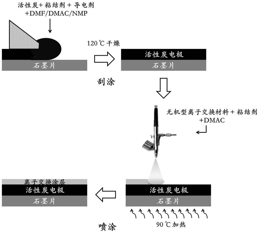
[0029] In other embodiments, the preparation method of the anion exchange layer includes: mixing the inorganic anion selective material with polyvinylidene fluoride, and spraying it on the surface of the porous carbon layer of the anode current collector; the cation exchange layer The preparation method includes: mixing the inorganic cation selective material with polyvinylidene fluoride (PVDF), dispersing it in N,N-dimethylacetamide (DMAC), and spraying it on the porous carbon layer of the cathode current collector surface. In these examples, after the powders of cation exchange materials and anion exchange materials are ball milled, the N,N-dimethylacetamide dispersion containing cation exchange materials and binder polyvinylidene fluoride is uniformly covered by ultrasonic spraying On the surface of the porous carbon layer of the cathode, the N,N-dimethylacetamide dispersion liquid of the anion exchange material and polyvinylidene fluoride is evenly covered on the surface o...

Embodiment 1

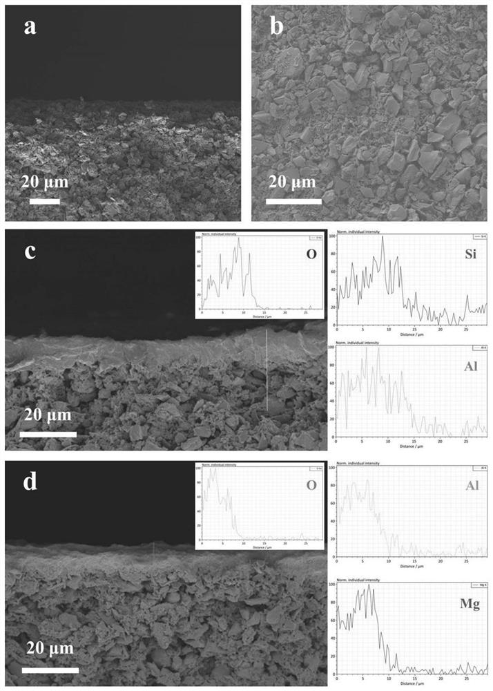
[0039] Example 1: Commercial activated carbon, conductive agent acetylene black and binder PVDF were used to prepare activated carbon electrodes, and the thickness of the electrodes was controlled to be between 100 and 200 microns. Using montmorillonite and PVDF mixed in a ratio of 5:1 to prepare a cation exchange coating on the surface of the cathode by ultrasonic spraying, using a mixture of hydrotalcite and PVDF in a ratio of 10:1 to prepare an anion exchange coating on the surface of the anode by ultrasonic spraying, ion exchanger The load was 1 mg / cm2. For surface characterization of ion exchange coatings see figure 2 , compared to the single-layer uniform structure of the pristine activated carbon electrode (4a), the composite electrodes (4c and 4d) both showed a layered structure with a dense upper layer and a porous lower layer. Through element detection, it can be found that the upper layer of the montmorillonite-coated electrode contains abundant Si, Al, and O elem...

Embodiment 2

[0041] Example 2: Commercial activated carbon, conductive agent acetylene black and binder PVDF were used to prepare activated carbon electrodes, and the thickness of the electrodes was controlled to be between 100 and 200 microns. Mix montmorillonite and PVDF in a ratio of 3:1 to prepare a cation-exchange coating on the surface of the cathode by ultrasonic spraying, use a mixture of hydrotalcite and PVDF in a ratio of 5:1 to prepare an anion-exchange coating on the surface of the anode by ultrasonic spraying, ion exchanger The load was 2 mg / cm2. Select simulated brine (initial concentration is 500 mg / L sodium chloride solution). Under normal temperature and pressure, a given constant voltage of 1.2 volts is charged for 15 minutes for adsorption and desalination, and a given constant voltage of 0 volts is discharged for 15 minutes for desorption and desalination, which is a complete cycle. Using unidirectional continuous flow, the system continues to work for more than 50 hou...


PUM

PropertyMeasurementUnit
Thicknessaaaaaaaaaa

Abstract

The invention discloses a capacitive deionization unit. The capacitive deionization unit comprises an anode current collector and a cathode current collector which are arranged at an interval, porous carbon layers are arranged on the surface of the anode current collector and the surface of the cathode current collector, and the surface of the porous carbon layer of the anode current collector is covered with an anion exchange layer. The surface of the porous carbon layer of the cathode current collector is covered with a cation exchange layer, the anion exchange layer is made of an inorganic anion selective material, and the cation exchange layer is made of an inorganic cation selective material. The invention further provides a capacitive deionization device and method. According to the invention, the same ion effect can be inhibited, the partial Faraday effect can be relieved, the coulombic efficiency of the desalination process in the capacitive deionization technology can be improved, the desalination amount is increased, the energy consumption is reduced, the desalination stability is improved, the service life of the electrode is prolonged, the device cost is reduced, and the pollution of organic matters to the porous carbon layer can be avoided.

Description

technical field [0001] The invention relates to the related technical field of desalination of water resources. More specifically, the present invention relates to a capacitive deionization unit, apparatus and method. Background technique [0002] Capacitive deionization technology is a process of electroadsorption and storage of ions based on the principle of an electric double layer. A certain potential difference is applied between the anode and the cathode, the anode adsorbs anions, and the cathode adsorbs cations to realize the separation of water and ions. It is a deionization technology with low consumption, low process cost and no secondary pollution. However, some existing technologies introduce an anion exchange membrane on the outside of the anode, and add a cation exchange membrane on the outside of the cathode. The ion exchange membrane blocks the repulsion of the same ion and also inhibits the occurrence of some side reactions. This method greatly improves the...

Claims


Application Information

Patent Timeline
IPC IPC(8): C02F1/469B01D61/42
CPCC02F1/4691C02F1/4698B01D61/427C02F2201/46
Inventor 梁大为吴擎昊卢善富张劲相艳
Owner BEIHANG UNIV
Learn More