Straight waveguide phase modulator, integrated assembly and preparation method

A phase modulator and straight waveguide technology, applied in instruments, voltage/current isolation, measurement devices, etc., can solve the reliability of fiber optic current transformers, the impact of assembly complexity, the impact of manufacturing costs, different coupling efficiencies, and the impact of contrast. Achieve the effect of reducing the complexity of optical path assembly, improving system reliability, and reducing fiber splicing points

Pending Publication Date: 2021-08-20
天津领芯科技发展有限公司
View PDF0 Cites 1 Cited by
  • Summary
  • Abstract
  • Description
  • Claims
  • Application Information

AI Technical Summary

Problems solved by technology

The existence of the optical path difference between two linearly polarized light waves will inevitably affect the time reciprocity of the optical path of the fiber optic current transformer
[0007] (2) Due to the difference in the ion diffusion rate along the ordinary optical crystal axis and the extraordinary optical crystal axis of lithium niobate crystal, there are differences in the distribution of TE and TM optical waveguide modes (that is, the spot size). On the one hand, it will cause light waves with different polarization states The transmission loss experienced in the waveguide is different, on the other hand, it will also cause the coupling efficiency of light waves with different polarization states to be different at the fiber coupling point, which will eventually have a great impact on the contrast of the interference optical signal of the orthogonally polarized light waves
Too many fiber splicing points and too many discrete fiber passive / active components will inevitably have a great impact on the reliability, assembly complexity and manufacturing cost of the fiber optic current transformer

Method used


Image

  • Straight waveguide phase modulator, integrated assembly and preparation method
  • Straight waveguide phase modulator, integrated assembly and preparation method
  • Straight waveguide phase modulator, integrated assembly and preparation method

Examples


Embodiment 1

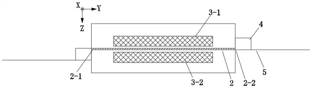
[0069] refer to figure 2 , shown in the figure is a schematic structural diagram of the straight waveguide phase modulator provided by this embodiment. A straight waveguide phase modulator, comprising: a lithium tantalate base wafer 1, which has an electro-optical effect; a straight waveguide 2, which is a zinc oxide diffused optical waveguide, formed in the lithium tantalate base wafer 1; a metal electrode 3, used for The light wave transmitted in the straight waveguide 2 is modulated; the optical fiber crystal carrier block 4 is made with a groove on the surface or a round hole in the center for placing the polarization maintaining optical fiber 5, which is formed on the lithium tantalate substrate wafer 1 after polishing Straight waveguides in 2-coupling bonding.

[0070] As the base wafer and the substrate medium used to form the optical waveguide, the lithium tantalate base wafer 1 is an optical-grade crystal material. Lithium tantalate crystal materials with the same ...

Embodiment 2

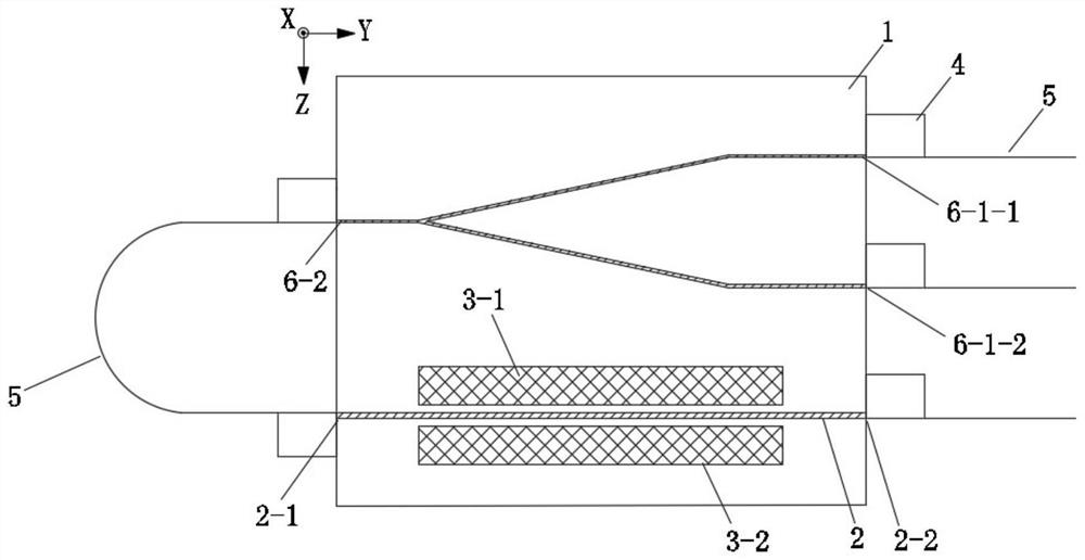
[0079] refer to image 3 , which is a schematic structural diagram of an embodiment of the integrated component provided by this embodiment. An integrated component includes: a lithium tantalate base wafer 1 , a straight waveguide 2 , a metal electrode 3 , an optical fiber crystal carrier block 4 , a polarization-maintaining optical fiber 5 , and a Y-branch waveguide coupler 6 . Among them, the structures of the lithium tantalate base wafer 1 , the straight waveguide 2 , the metal electrode 3 , and the optical fiber crystal carrier block 4 are the same as in the embodiment 1, and will not be described in detail here.

[0080] The Y-branch waveguide coupler 6 integrates two important functions of the waveguide coupler and the waveguide polarizer, among which: the function of the waveguide coupler is realized through the Y-branch structure; Feature implementation.

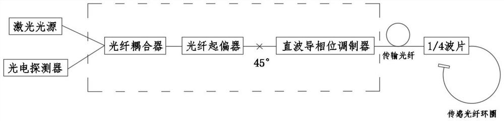
[0081] refer to image 3 , this embodiment can be figure 1 Each discrete optical fiber device in the dotted bl...

Embodiment 3

[0084] refer to Figure 5 , which is a schematic structural diagram of the integrated components provided by this embodiment. In order to further improve the integration of integrated components, improve the reliability of components, reduce assembly difficulty and manufacturing cost, on the basis of Embodiment 2, this embodiment improves the fiber crystal carrier block 4 by adopting multi-channel fiber crystal carrier block 4 and place a polarization-maintaining optical fiber 5 in each channel to form a multi-channel optical fiber array.

[0085] Specifically, it includes: a lithium tantalate base wafer 1 , a straight waveguide 2 , a metal electrode 3 , an optical fiber crystal carrier block 4 , a polarization-maintaining optical fiber 5 , and a Y-branch waveguide coupler 6 . Among them, the structures of the lithium tantalate base wafer 1 , the straight waveguide 2 , the metal electrode 3 , and the Y-branch waveguide coupler 6 are the same as those in Embodiment 2, and will...


PUM

PropertyMeasurementUnit
thicknessaaaaaaaaaa
widthaaaaaaaaaa
thicknessaaaaaaaaaa

Abstract

The invention discloses a straight waveguide phase modulator, an integrated assembly and a preparation method. A lithium tantalate crystal with a smaller birefringence effect is used as a substrate crystal of the straight waveguide phase modulator, the optical path difference of orthogonal polarization light waves is smaller, and the transmission loss and the coupling loss related to polarization are lower. In addition, a Y-branch waveguide coupler with the functions of a polarizer and a coupler and a straight waveguide phase modulator are integrated on the same lithium tantalate wafer. An optical fiber current transformer system based on the integrated assembly is higher in reliability, lower in assembly complexity and lower in manufacturing cost.

Description

technical field [0001] The invention can be applied to the technical field of optical fiber current transformers, and in particular relates to a direct waveguide phase modulator, an integrated component and a preparation method. Background technique [0002] The all-fiber optic current transformer based on the Faraday magneto-optical effect has the characteristics of strong insulation, small size, light weight, large dynamic range, and full digitalization. It has more prominent advantages in power and electrical systems that require higher automation, higher electrical equipment automation, and stronger insulation capabilities. Common optical fiber current transformers mainly include three technical solutions: Sagnac interference optical circuit based on Y waveguide phase modulator, collinear optical circuit based on Y waveguide phase modulator and collinear optical circuit based on straight waveguide phase modulator, among which The optical path of the collinear fiber opti...

Claims


Application Information

Patent Timeline
Patent Type & Authority Applications(China)
IPC IPC(8): G01R15/24
CPCG01R15/241
Inventor 李萍
Owner 天津领芯科技发展有限公司
Why Eureka
Try Eureka