High-energy beam scanning path planning method and additive manufacturing method and device

A technology of scanning path and additive manufacturing, which is applied in the field of additive manufacturing, and can solve problems such as suspension of forming process, powder blowing, and poor forming quality

Active Publication Date: 2021-09-07
西安赛隆增材技术股份有限公司
View PDF13 Cites 4 Cited by
  • Summary
  • Abstract
  • Description
  • Claims
  • Application Information

AI Technical Summary

Problems solved by technology

At present, the most common melting scanning path is linear zigzag scanning. This scanning method can form dense parts better, but the temperature field distribution during the forming process is very uneven, resulting in a large temperature gradient. Under the action of thermal stress generated by a large temperature gradient, it is easy to cause deformation and cracking
There is also a point-scanning path planning method, but this method is usually only used for part delineation, which limits the contour accuracy or loose layer of the formed part, and in the point-scanning mode, the high-energy beam scans a single point and then quickly deflects to the next position Dotting, this method is very easy to impact and splash the powder spread at the predetermined position, and it is easy to cause "powder blowing" and other phenomena, resulting in poor forming quality or even the suspension of the forming process

Method used


Image

  • High-energy beam scanning path planning method and additive manufacturing method and device
  • High-energy beam scanning path planning method and additive manufacturing method and device
  • High-energy beam scanning path planning method and additive manufacturing method and device

Examples


Embodiment Construction

[0044] Example embodiments will now be described more fully with reference to the accompanying drawings. Example embodiments may, however, be embodied in many forms and should not be construed as limited to the examples set forth herein; rather, these embodiments are provided so that this disclosure will be thorough and complete and will fully convey the concept of example embodiments to those skilled in the art. The described features, structures, or characteristics may be combined in any suitable manner in one or more embodiments.

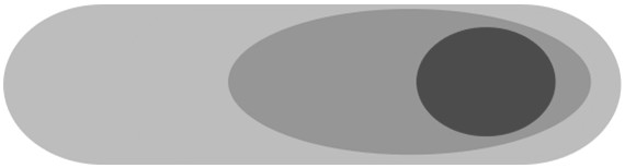
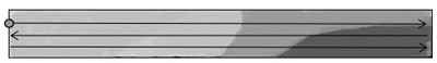
[0045]Please refer to Figure 1. Figure 1 is a schematic diagram of the temperature distribution after linear scanning in the existing additive manufacturing technology. Figure 1(a) is a diagram of the temperature gradient distribution during the scanning melting process of the molten pool generated by the high-energy beam. The darker the color in the figure, the higher the temperature. It can be seen that the temperature near the front of the mo...


PUM

PropertyMeasurementUnit
lengthaaaaaaaaaa
thicknessaaaaaaaaaa
pore sizeaaaaaaaaaa

Abstract

The invention relates to a high-energy beam scanning path planning method and an additive manufacturing method and device, and relates to the technical field of additive manufacturing. The high-energy beam scanning path planning method comprises the following steps that a three-dimensional model of an additive manufacturing part is constructed; the three-dimensional model of the part is layered and sliced in the printing and manufacturing direction, and section contour data of each layer of slice are extracted; a contour line of each layer of slice is obtained according to the section contour data of each layer of slice, and at least one continuous scanning line is obtained after the contour lines are contracted inwards or expanded outwards; the scanning line is randomly divided into N sections, wherein the length of each scanning line section is smaller than or equal to a preset value; and each scanning line section is numbered, each scanning line section is scanned according to a preset numbering scanning sequence, and at least one scanning line segment is arranged between every two scanning line sections which are scanned in sequence. The uniformity of heat distribution during additive manufacturing of thin-wall parts is improved, the thermal stress is reduced, and deformation and cracking of the parts are prevented.

Description

technical field [0001] The invention relates to the technical field of additive manufacturing, in particular to a high-energy beam scanning path planning method, an additive manufacturing method and an additive manufacturing device. Background technique [0002] High melting point metal materials, such as tungsten and tungsten alloys, molybdenum and molybdenum alloys, nickel-based superalloys, etc., have the characteristics of high melting point and boiling point, high hardness, low expansion coefficient, low vapor pressure, etc. There are important applications in industry and other extreme environment fields. However, due to the high melting point and low-temperature brittleness of high-melting-point metal materials such as tungsten and molybdenum, it is difficult to prepare them by common casting and machining methods. Usually, most parts made of refractory materials such as tungsten and molybdenum are prepared by powder metallurgy, but conventional sintered products hav...

Claims


Application Information

Patent Timeline
Patent Type & Authority Applications(China)
IPC IPC(8): B22F10/366B22F10/85B22F12/40B33Y10/00B33Y30/00B33Y50/02
CPCB22F10/366B22F10/85B22F12/40B33Y10/00B33Y30/00B33Y50/02Y02P10/25
Inventor 李会霞朱纪磊车倩颖程康康王宇
Owner 西安赛隆增材技术股份有限公司
Why Eureka
Try Eureka