Fixed bed continuous upper suction gasification furnace for waste disposal

A fixed bed and waste technology, applied in the field of gasifier, can solve the problems of narrowing the scope of application of the furnace, not being able to discharge large residues, and short incineration time

Active Publication Date: 2021-09-14
上海海琦环保科技有限公司
View PDF12 Cites 2 Cited by
  • Summary
  • Abstract
  • Description
  • Claims
  • Application Information

AI Technical Summary

Problems solved by technology

Causes an increase in the cost of subsequent flue gas purification
[0005]Secondly, due to the high-temperature combustion, the ash, metal and other non-combustible substances of the garbage are in a molten state, and slagging occurs during the cooling process, and sometimes the volume is large, resulting in discharge The slag is difficult, and the slag breaking mechanism must be added, which increases the complexity of the furnace and increases the cost of manufacturing and using the furnace
At the same time, due to high-temperature incineration and short incineration time, the slag is still mixed with unburned combustible substances, which increases the difficulty of harmless treatment of the slag in the later stage
[0006]Furthermore, different wastes have different combustion characteristics and requirements, so to maintain high-temperature combustion, there are different requirements for the structure and process parameters of the furnace, which narrows the The scope of application of the furnace
[0007]At the same time, because most of the waste contains iron products, it cannot be gasified, but the feed end of the current gasifier lacks these iron products The results collected, and most of the current grate frames are fixed structures, which cannot discharge the larger residues, so that they cannot meet the needs of people.

Method used


Image

  • Fixed bed continuous upper suction gasification furnace for waste disposal
  • Fixed bed continuous upper suction gasification furnace for waste disposal
  • Fixed bed continuous upper suction gasification furnace for waste disposal

Examples


Embodiment 1

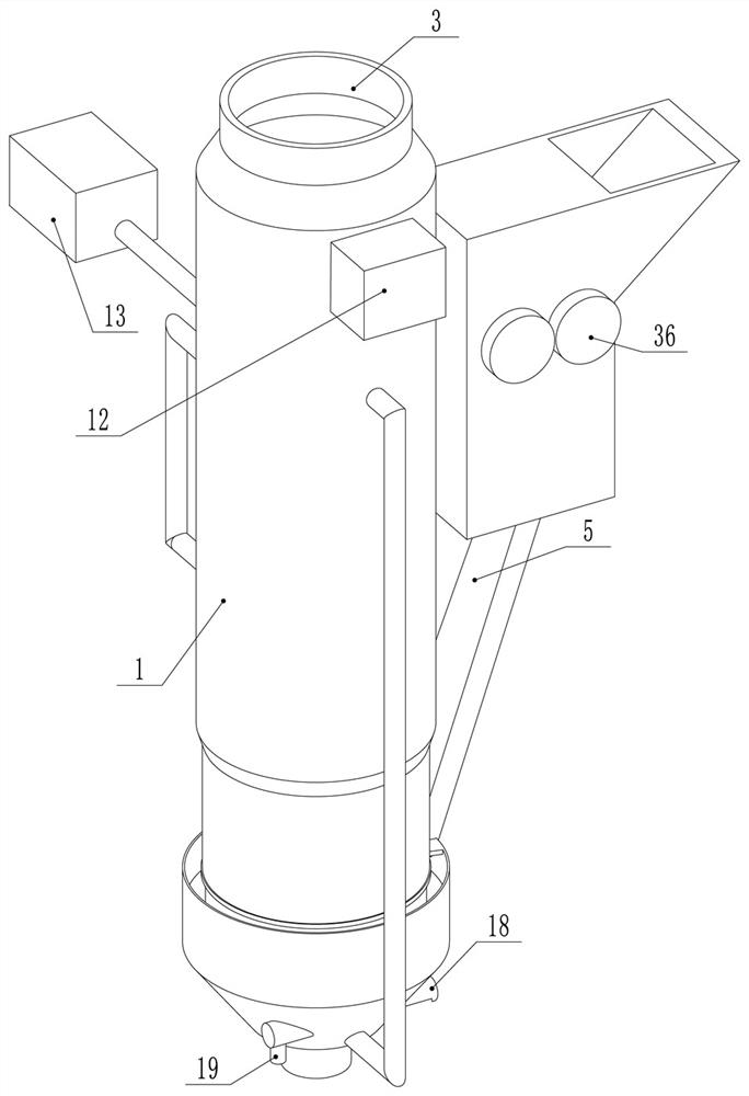
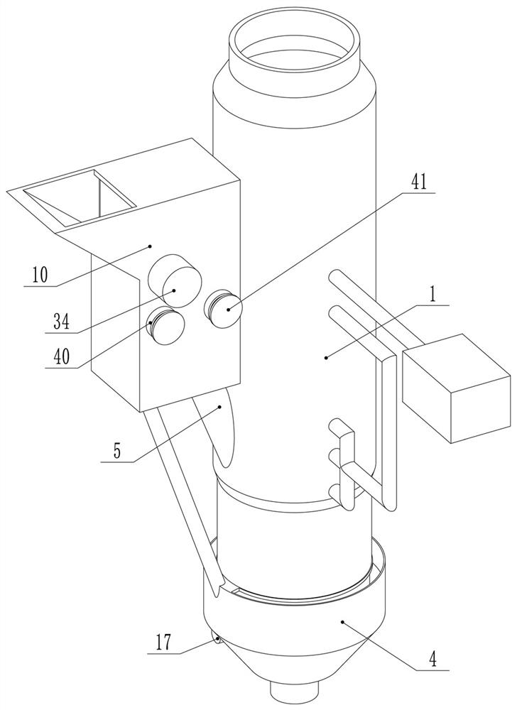
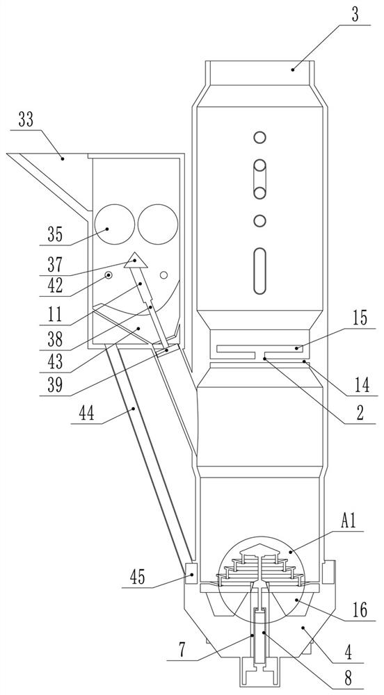
[0041] Embodiment 1, a fixed-bed continuous up-suction gasifier for waste treatment, when in use, puts the waste to be treated into the inside of the feed bin 10, and then makes the crushing motor 34 work, thereby improving the The waste is crushed, and the iron products in the waste are collected by the magnetic rod 42, and then the electric push rod 38 is reciprocated, so that the waste is added to the inside of the feeding pipe 5, and the material is fed along the feeding pipe. 5 Entering the interior of the furnace body 1, the waste entering the furnace body 1 forms a combustion layer at the bottom of the furnace body 1, and forms an oxide layer, a thermal contact layer and a drying layer in sequence above the combustion layer. The water vapor, volatile gas and combustible mixed gas generated by the cracking of garbage in the pyrolysis layer are collectively referred to as flue gas and the air inside the dispersion pipe 51 enters the secondary combustion chamber for combust...


PUM


Abstract

The invention discloses a fixed bed continuous upper suction gasification furnace for waste disposal. The fixed bed continuous upper suction gasification furnace comprises a furnace body, a dispersion frame is installed inside the furnace body, an exhaust port is formed in the top end of the furnace body, a storage bin is installed at the bottom end of the furnace body, and a feeding pipe is installed on the side surface of the furnace body. A new process of low temperature pyrolysis incineration is adopted, garbage is dried, pyrolyzed and combusted in the furnace at low temperature, so that the defects caused by high-temperature combustion are avoided, the garbage is fully combusted, heat energy is fully utilized, non-smelting slag such as non-combustible ash content can reach a higher combustion efficiency through a novel structure of the furnace on the basis of fully restraining generation of harmful substances such as dioxin, polycyclic hydrocarbon, aldehydes and carbon dioxide, iron products can be conveniently collected and prevented from entering the interior of the furnace body through arranged magnetic bars, and larger residues can be conveniently discharged through arrangement of a adjustable grate frame structure.

Description

technical field [0001] The invention relates to the technical field of gasification furnaces, in particular to a fixed-bed continuous up-suction gasification furnace for waste treatment. Background technique [0002] Commonly used waste incinerators generally use high-temperature combustion, which can not only improve the efficiency of the incinerator, but also decompose harmful gases such as dioxin at high temperature for harmless treatment. [0003] However, due to high-temperature combustion, the burning time of garbage in the furnace becomes shorter, and the following disadvantages appear: [0004] First of all, due to high-temperature combustion, thermal radiation, heat convection and other heat exchanges are improved, and at the same time, a considerable part of the available combustible substances and combustible gases are directly incinerated without being used, thereby reducing the utilization rate of heat energy. At the same time, in order to achieve full combusti...

Claims


Application Information

Patent Timeline
IPC IPC(8): F23G5/033F23G5/02F23G5/027F23G5/16F23G5/44F23G5/50F23J1/00F23L15/00
CPCF23G5/033F23G5/44F23G5/444F23G5/02F23G5/027F23L15/00F23G5/165F23G5/50F23J1/00F23G2201/60F23G2201/80Y02E20/34
Inventor 苏振江苏奇郑晓霖
Owner 上海海琦环保科技有限公司
Why Eureka
Try Eureka