
Electroplating wastewater treatment system and process

A technology of electroplating wastewater and treatment system, which is applied in metallurgical wastewater treatment, water/sewage treatment, biological water/sewage treatment, etc. It can solve the problems of secondary pollution, adsorbent regeneration, high energy consumption, etc., to avoid pipeline blockage, Reduce the load of water inflow and the effect of no secondary pollution

Inactive Publication Date: 2021-09-24
GUANGZHOU EP ENVIROMENTAL ENG
View PDF4 Cites 0 Cited by
  • Summary
  • Abstract
  • Description
  • Claims
  • Application Information

AI Technical Summary

Problems solved by technology

Among them, the vacuum evaporation method consumes a lot of energy and has relatively strict operating parameters; although the chemical precipitation method has low operating costs and is easy to operate, the solid waste generated requires secondary treatment and is likely to cause secondary pollution; electrodialysis, The reverse osmosis method has high investment cost and high energy consumption, and the membrane used is easily polluted; the ion exchange method has a large investment and complicated process; the membrane separation method is costly and will cause membrane pollution; the adsorption method has strict conditions and is only suitable for low-concentration wastewater At the same time, there are problems such as the regeneration of the adsorbent; the conventional chemical precipitation method has low cost, simple operation, and wide application, but it is difficult to meet the increasingly stringent emission standards. In the actual treatment process, it needs to be combined with membrane treatment, ion exchange and other processes. It is difficult to be widely used for in-depth processing, which increases the processing cost

Method used


Image

  • Electroplating wastewater treatment system and process
  • Electroplating wastewater treatment system and process
  • Electroplating wastewater treatment system and process

Examples


Embodiment 1

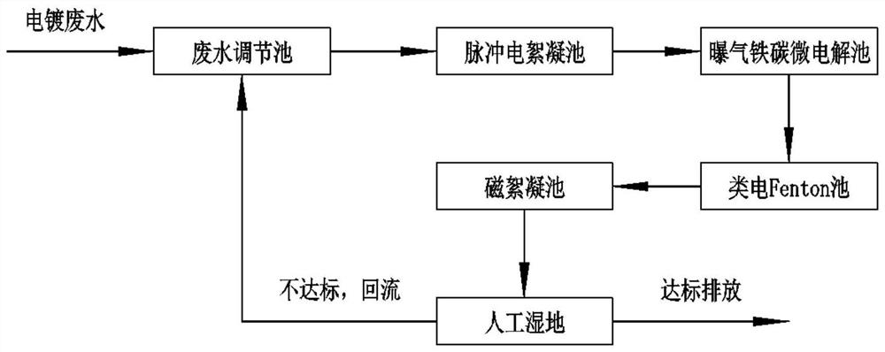
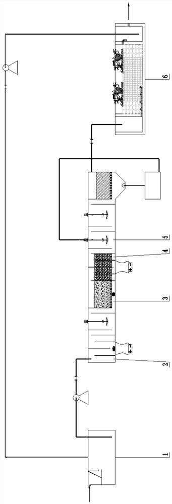
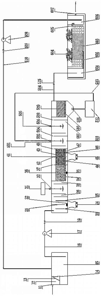
[0102] A system for treating electroplating wastewater, such as figure 2 and image 3 As shown, it includes a regulating tank 1 with a water inlet 11, a pulse electroflocculation tank 2, an aerated iron-carbon internal electrolytic tank 3, a similar electric Fenton tank 4, a magnetic flocculation tank 5 and a constructed wetland 6 with a discharge port 607 .

[0103] Wherein, the regulating pool 1 provided with the water inlet 11 includes the water inlet 11, the grid pool 12, the fine grid net 13, the first water outlet 14, the liquid collection pool 15, the riser 16, the first lift pump 17, the first valve 18;

[0104] The pulse electrocoagulation cell 2 includes a first separator 21, a pulse device 22, a first anode 23, a first stabilized DC power supply 24, a first cathode 25, and a second water outlet 26;

[0105] The aerated iron-carbon internal electrolytic cell 3 includes an acid dosing tank 31, a first agitator 32, a third water outlet 33, a first water guide orifi...


PUM


Abstract

The invention provides an electroplating wastewater treatment system and process, and relates to the technical field of wastewater treatment. The electroplating wastewater treatment system provided by the invention comprises an adjusting tank, a pulse electric flocculation tank, an aeration iron-carbon internal electrolytic tank, an electro-Fenton-like tank, a magnetic flocculation tank and an artificial wetland which are connected in sequence; wherein the regulating tank can be used for removing large-particle impurities in the electroplating wastewater and carrying out preliminary precipitation on the wastewater; the pulse electric flocculation basin can flocculate and precipitate heavy metals, cyanides, COD and the like in the wastewater; the aeration iron-carbon internal electrolytic tank can be used for removing cyanide, COD (Chemical Oxygen Demand) and the like in the wastewater; the electro-Fenton-like pool can further remove refractory organic matters and the like; the magnetic flocculation basin can further flocculate and precipitate heavy metals, nitrate and the like in the wastewater; and the artificial wetland can be used for carrying out nitrogen and phosphorus removal on the wastewater. According to the electroplating wastewater treatment system disclosed by the invention, all the treatment units are matched with one another, so that the purpose of beautifying the environment is achieved.

Description

technical field [0001] The invention relates to the technical field of wastewater treatment, in particular to an electroplating wastewater treatment system and process. Background technique [0002] The electroplating industry is one of the three major polluting industries today. The composition of the production wastewater is complex, there are many toxic and harmful substances, the concentration of pollutants is high, and the biodegradability is poor. The main pollutants are heavy metals (Cu, Ni, Cr, Zn and Cd), cyanide , organic matter, etc., has become one of the most serious environmental pollution problems today. At the same time, in order to ensure the stability, service life and quality of the coating, electroplating companies have added a lot of complexing agents, stabilizers, accelerators, etc. Cu 2+ 、Ni 2+ Form stable coordination complexes, etc., which often lead to unsatisfactory treatment effects for COD and heavy metal ions. [0003] There are different tr...

Claims


Application Information

Patent Timeline
IPC IPC(8): C02F9/14C02F103/16C02F103/06C02F101/30C02F101/20C02F101/18C02F101/22
CPCC02F9/00C02F2103/16C02F2103/06C02F1/463C02F1/46176C02F1/46104C02F1/4672C02F1/66C02F1/72C02F1/76C02F1/4674C02F1/488C02F1/52C02F1/5281C02F3/32C02F3/34C02F1/56C02F1/5236C02F2101/20C02F2101/18C02F2101/30C02F1/722C02F1/001C02F2101/22
Inventor 周文栋谢永新李锐敬陈益成雒怀庆徐波黄睦凯伦见强李小强杨炜雯
Owner GUANGZHOU EP ENVIROMENTAL ENG
Learn More