Device and method for treating organic waste gas by coupling ultraviolet light catalysis with microorganisms

A technology for microbial treatment and organic waste gas, applied in chemical instruments and methods, chemical/physical processes, separation methods, etc., can solve the difficulty of biological treatment of organic pollutants, the loss of advantages of advanced oxidation-biodegradation, and the difficulty in controlling intermediate products. and other problems, to achieve the effect of shortening the processing cycle, compact structure and simple operation

Active Publication Date: 2021-10-01
CHINA UNIV OF MINING & TECH
8 Cites 0 Cited by

AI-Extracted Technical Summary

Problems solved by technology

Advanced oxidation pretreatment aims to improve the biodegradability, however, its reaction speed is very fast, it is very difficult to control the intermediate products to the biodegradable stage, and the excessi...

Method used

As shown in Fig. 1, Fig. 2, a kind of ultraviolet photocatalytic coupling microorganism of the present invention is processed the device of organic waste gas, comprises ultraviolet photocatalytic coupling microbial reactor, circulating liquid storage tank 17 and circulating pump 18, described ultraviolet The photocatalytic coupled microbial reactor includes a housing 5, the housing 5 is made of p...

Abstract

The invention discloses a device and method for treating organic waste gas through ultraviolet light catalysis coupling microorganisms. The device comprises an ultraviolet light catalysis coupling microorganism reactor, a circulating liquid storage tank and a circulating pump, and at least two filler layers are sequentially arranged in the reactor from bottom to top; the filler layer is a sponge carrier loaded with an efficient degrading flora and an Ag/WO3 catalyst. According to the invention, on the basis of ultraviolet light catalytic oxidation enhanced biodegradation, organic gas can be synchronously treated in three modes of ultraviolet light catalytic oxidation, biodegradation and ultraviolet light catalytic oxidation-biodegradation direct coupling, the structure is simple and compact, and the operation is simple; the device can operate continuously and efficiently, is low in energy consumption and cost, and has high organic gas purification efficiency.

Application Domain

Gas treatmentOrganic-compounds/hydrides/coordination-complexes catalysts +2

Technology Topic

ChemistryExhaust fumes +9

Image

  • Device and method for treating organic waste gas by coupling ultraviolet light catalysis with microorganisms
  • Device and method for treating organic waste gas by coupling ultraviolet light catalysis with microorganisms
  • Device and method for treating organic waste gas by coupling ultraviolet light catalysis with microorganisms

Examples

  • Experimental program(2)

Example Embodiment

[0032] Example 1
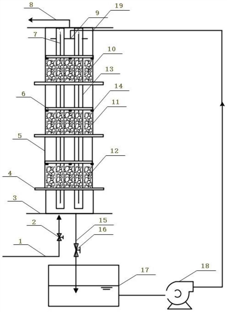
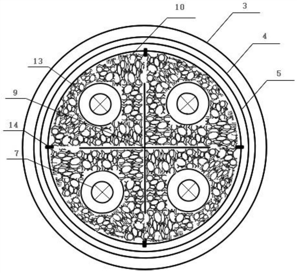
[0033] like figure 1 , figure 2 As shown, a device for treating organic waste gas with ultraviolet photocatalytic coupling microorganisms of the present invention includes an ultraviolet photocatalytic coupling microbial reactor, a circulating liquid storage tank 17 and a circulation pump 18, and the ultraviolet photocatalytic coupling microbial reactor includes a housing 5. The housing 5 is made of plexiglass, the bottom of the housing 5 is provided with an air inlet 1 and a liquid outlet 15, and the top of the housing 5 is provided with an air outlet 8 and a liquid inlet 19. The upper part of the casing 5 is also provided with a spraying device 9, which communicates with the liquid inlet 19. The spraying device 9 in this embodiment is preferably cross-shaped, and the spraying is more uniform.
[0034]The inside of the housing 5 is provided with at least two filler layers sequentially from bottom to top, and the filler layers are loaded with highly efficient degrading bacteria and Ag/WO 3 The sponge carrier of the catalyst is also vertically provided with a plurality of ultraviolet lamp tubes 7 inside the housing 5, and four ultraviolet lamp tubes 7 are preferably set in the present embodiment, such as figure 2 As shown, four ultraviolet lamp tubes 7 are arranged in parallel at equal intervals to form a square. The ultraviolet lamp tube 7 is located in a quartz sleeve 13, and the quartz sleeve 13 is embedded in a packing layer.
[0035] The bottom of the packing layer is supported by a perforated quartz glass plate-4, and at least three fixing piles 14 are arranged above the packing layer. In this embodiment, four fixing piles 14 are preferably arranged. A perforated quartz glass plate 2 6 that can move up and down is placed on the fixed pile 14. The perforated quartz glass plate 1 6 and the perforated quartz glass plate 2 14 are all provided with a large hole for the quartz sleeve 13 to pass through. For the holes and the small holes for the liquid to pass through, the diameter of the large hole is adapted to the outer diameter of the quartz sleeve 13, the diameter of the small hole is 3mm, and the opening ratio of the small hole is 60%.
[0036] In this embodiment, three packing layers are preferably provided, which are respectively the first packing layer 10 , the second packing layer 11 and the third packing layer 12 from bottom to top.
[0037] The circulating liquid storage tank 17 is filled with inorganic salt nutrient solution, and the liquid inlet 19 and the liquid outlet 15 of the ultraviolet photocatalytic coupling microbial reactor are respectively connected with the circulating liquid storage tank 17 through pipelines. The circulating pump 18 is arranged on the connecting pipeline between the circulating liquid storage tank 17 and the liquid inlet 19 .
[0038] Preferably, the pipeline connected to the air inlet 1 is provided with an air intake valve 2, through which the flow rate of the incoming gas is adjusted, and the pipeline connected with the liquid outlet 15 is provided with a liquid discharge valve 16, through which Drain valve 16 controls the discharge of liquid in the reactor.
[0039] In the above examples, the load is loaded with highly efficient degrading bacteria and Ag/WO 3 The preparation process of the sponge carrier of catalyst comprises:
[0040] (1) Take 5g photocatalyst Ag/WO 3 , dissolved in 150mL of absolute ethanol, put it into a beaker, and ultrasonicated for 10min to make Ag/WO 3 The catalyst is evenly distributed in the beaker.
[0041] (2) Weigh 4g of granular polyurethane carrier with a size of 5mm*5mm*5mm and 2g of agar powder (vegetable glue with viscousness, which is helpful for microbial load in later experiments) and put them into a beaker to disperse evenly, and ultrasonically again for 15min to make Ag/ WO 3 The catalyst is uniformly dispersed around the carrier.
[0042] (3) Put the ultrasonically dispersed mixture into an oven at 85°C and stir once every 25 minutes so that the catalyst in the solution does not settle to the bottom of the cup. 3 The catalyst is supported on the carrier.
[0043] (4) Submerge the loaded carrier in deionized water, ultrasonically treat it for 5 minutes to remove the loose catalyst on the surface of the polyurethane sponge, and then place it in an oven at 55°C for drying. Ag/WO 3 The photocatalyst was successfully loaded on the carrier.
[0044] (5) The temperature is kept at 25°C, and the intake concentration of chlorobenzene is kept at 120mg/m 3 , the spray volume is set to 20L/d, in the inorganic salt nutrient solution (formula composition is NH 4 Cl 0.5g/L, NaH 2 PO 4 ·H 2 O 1g/L, KH 2 PO 4 1g/L, MgSO 4 ·7H 2 O 1g/L, CaCl 2 0.02g/L, FeSO 4 ·7H 2 O 5mg/L, ZnSO 4 ·7H 2 O 4mg/L MnCl 2 4H 2 O 0.2mg/L, CoCl 2 ·6H 2 O0.5mg/L, NiCl 2 ·6H 2 O 0.1mg/L, H 3 BO 3 0.15mg/L, ethylenediaminetetraacetic acid 2.5mg/L, pH 7±0.2) inoculated with highly efficient degrading bacteria, loaded with Ag/WO 3 The carrier of the photocatalyst is placed in a UV-photocatalytic coupled microbial reactor for circulating fluidized film formation. After 30 days of continuous cycle of film hanging, the exterior and interior of the polyurethane sponge carrier are covered with biofilm. The ultraviolet light is irradiated for 6 hours, so that the biofilm on the surface of the polyurethane sponge carrier that can be irradiated by the ultraviolet light falls off to expose the photocatalyst, and the polyurethane sponge carrier that simultaneously supports the catalyst and the biofilm is obtained.
[0045] Among them, the source of efficient degrading bacteria is the activated sludge of Xuzhou Coking Plant. The co-domestication mode of "intermediate product-target pollutant" is used for directional domestication, the content of chlorobenzene and catechol gradually increases, and the content of glucose gradually decreases, and it is adjusted every 3 days according to the plan, so that microorganisms can adapt to chlorobenzene The toxic environment of the gas, and can degrade the intermediate product. The acclimatization scheme of microorganisms is shown in Table 1.
[0046] Table 1 Microbial acclimatization program
[0047]
[0048] After domestication, through high-throughput sequencing analysis, it was found that Lysinibacillus (Bacillus pumilus), Pseudomonas (Pseudomonas), and Achromobacter (Achromobacter) were mainly efficient degrading bacteria, accounting for 43.7% and 32.9% respectively. %, 13.1%.
[0049] image 3 a is the SEM image of the original polyurethane sponge carrier. It can be seen that the original catalyst carrier skeleton has a smooth surface, a large internal space, and a pore diameter between 120-320 μm. image 3 b is the load Ag/WO 3 The SEM picture of the polyurethane sponge carrier of the catalyst, it can be seen that Ag/WO 3 The catalyst was successfully and evenly loaded on the sponge skeleton, with few cracks and no large-area stacking. In addition, Ag/WO 3 The catalyst is attached to the surface of the polyester sponge, which does not block the important path for the attachment and growth of microorganisms, and can effectively block the damage of ultraviolet light to internal microorganisms. Compared with the smooth surface of the polyester sponge skeleton, the loaded Ag/WO 3 The surface of the carrier after the catalyst is relatively rough, which is more conducive to the growth of microorganisms to form a film. image 3 c is to simultaneously load highly efficient degrading bacteria and Ag/WO 3 The SEM image of the polyurethane sponge carrier of the catalyst, it can be clearly observed that the loaded Ag/WO 3 The surface of the carrier after the catalyst is covered with biofilm, which proves that the loading of Ag/WO 3 The catalyst carrier has successfully formed a membrane.
[0050] When in use, the organic gas enters from the air inlet 1, and enters the ultraviolet photocatalytic coupling microbial reactor through the air inlet valve 2 from bottom to top. Organic gases were loaded with highly efficient degrading bacteria and Ag-WO 3 The third packing layer 12, the second packing layer 11, and the first packing layer 10 of the catalyst, the ultraviolet photocatalytic oxidation reaction takes place on the upper and lower surfaces of each packing layer and the inside of the packing layer in contact with the ultraviolet lamp respectively, and the refractory large Molecules are oxidized to intermediate small molecular substances, which further diffuse to the inner surface of the filler and are further degraded by highly efficient degradation bacteria. During this process, due to the diffusion of organic gases, the direct degradation of organic gases by microorganisms occurs simultaneously in the packing layer loaded with highly efficient degrading bacteria. In addition, under the irradiation of ultraviolet lamps, a small amount of ozone is produced in the air, which promotes the growth of efficient degrading bacteria in the first packing layer 10, the second packing layer 11 and the third packing layer 12, and strengthens the degradation of organic gases by microorganisms. process.
[0051] The inorganic salt nutrient solution flows out from the circulating liquid storage tank 17, enters the ultraviolet photocatalytic coupled microbial reactor through the circulating pump 18 from the liquid inlet 19, and is evenly and slowly sprayed on the first packing layer 10 and the second packing layer by the spraying device 9. 11 and the third packing layer 12, the spray volume is set to 20L/d to provide necessary nutrients for the growth of highly efficient degrading bacteria. Finally, the liquid outlet 15 below the ultraviolet photocatalytically coupled microbial reactor flows back to the circulation liquid storage tank 17 through the liquid discharge valve 16 to complete the cycle.

Example Embodiment

[0052] Example 2
[0053] Utilize the treatment device of embodiment 1 to carry out chlorobenzene waste gas treatment, set only ultraviolet light irradiation as control group, experimental group is set to ultraviolet+Ag/WO 3 (UV Photocatalytic Oxidation), UV+Efficient Degrading Bacteria (Biodegradation), UV+Ag/WO 3 +Efficient degrading bacteria (UV photocatalytic oxidation-biological direct coupling).
[0054] The circulating fluid flow rate is 2.95×10 -5 m 3 /s, the column temperature is kept at 25°C, the empty bed residence time (EBRT) is controlled at 120s, and the initial concentration of chlorobenzene is 160mg/m 3 Under the condition of reaction 10h, the concentration of chlorobenzene in the control group basically did not change.
[0055] From 0 to 4 hours, the concentration of chlorobenzene in the experimental group loaded with biofilm almost did not decrease. After 4 hours of adaptation, the degradation effect of biofilm on chlorobenzene increased slowly.
[0056] UV+Ag/WO 3 The degradation rate of the experimental group reached 86.3% after 8 hours, and then remained in a stable state.
[0057] The degradation rate of p-chlorobenzene can reach 98.3%.
[0058] It can be seen that the UV photocatalytic oxidation-biological direct coupling treatment has obvious advantages over the single UV photocatalytic oxidation and biodegradation.

PUM

no PUM

Description & Claims & Application Information

We can also present the details of the Description, Claims and Application information to help users get a comprehensive understanding of the technical details of the patent, such as background art, summary of invention, brief description of drawings, description of embodiments, and other original content. On the other hand, users can also determine the specific scope of protection of the technology through the list of claims; as well as understand the changes in the life cycle of the technology with the presentation of the patent timeline. Login to view more.

Similar technology patents

Novel flywheel energy storage device

ActiveCN104410204AShorten the axial lengthcompact structure
Owner:JIANGSU UNIV

Novel wideband microband coupler based on defect place structure

InactiveCN101308946Alower resonant frequencycompact structure
Owner:INST OF ELECTRONICS CHINESE ACAD OF SCI

Automatic handing system of weight and application thereof

InactiveCN101806612AConvenient automatic handlingcompact structure
Owner:NAT INST OF METROLOGY CHINA

Roasted sausage and its production process

ActiveCN1810164ARuddy colorcompact structure
Owner:烟台喜旺肉类食品有限公司 +1

Classification and recommendation of technical efficacy words

  • easy to operate
  • compact structure

Lancet device

InactiveUS7303573B2inexpensively mass-producedeasy to operate
Owner:ABBOTT DIABETES CARE INC

Rapid and non-invasive optical detection of internal bleeding

InactiveUS20050065436A1easy to operaterapid and accurate result
Owner:HO WINSTON ZONH +2
Why Eureka
Try Eureka