
Continuous glass fiber reinforced polyurethane foam material forming process and system

A continuous glass fiber and foam material technology, applied in the field of polyurethane composite material preparation, can solve the problems affecting the mechanical properties of products, the inability to obtain reinforced polyurethane microcellular foam profiles, and high glass fiber density, and achieve the effect of full infiltration

Pending Publication Date: 2021-10-01
南京启华新材料科技有限公司 +1
View PDF6 Cites 2 Cited by
  • Summary
  • Abstract
  • Description
  • Claims
  • Application Information

AI Technical Summary

Problems solved by technology

[0004] First, high pressure is used to forcibly squeeze the polyurethane raw material between the reinforcing fibers, forcing the air that cannot be discharged to be squeezed between the reinforcing fibers and the resin, forming poor interfacial bonding, resulting in the mechanical properties of the finally obtained reinforced polyurethane profiles Poor; second, using high-pressure forced extrusion process, polyurethane can not be foamed at all, and reinforced polyurethane microcellular foam profiles cannot be obtained at all; third, due to the existing inherent molding process system, the mold is set horizontally, and the glass fiber is in the mold. Sagging in the middle, resulting in high density of glass fiber in the lower part of the inner cavity, low density in the upper part, and large pores, thus affecting its mechanical properties and poor mechanical properties. At the same time, through the ordinary glass fiber infiltration process, the infiltration effect is poor, which affects the mechanical properties of the final product

Method used


Image

  • Continuous glass fiber reinforced polyurethane foam material forming process and system
  • Continuous glass fiber reinforced polyurethane foam material forming process and system
  • Continuous glass fiber reinforced polyurethane foam material forming process and system

Examples


Embodiment 1

[0050] (1) Preparation of matrix raw materials: The weight parts of each raw material in the foaming system are calculated according to the following ratio to prepare the combined polyether, and after fully mixing, add it to the A storage tank;

[0051]

[0052] The formula for calculating the wettability of combined polyether is as follows:

[0053]

[0054] Among them, ρ 产品 is the density of the experimental product, ρ 标准 is the density of the standard product, S is the cross-sectional area of ​​the shaped product, n is the number of strands of glass fiber, and Tex is the mass of 1000m per strand of glass fiber;

[0055] The degree of infiltration of the combined polyether is calculated to be 99%;

[0056] The viscosity of the combined polyether is 300mPa.s at 40°C, and the average functionality is 3.2;

[0057] At the same time, isocyanate is added in storage tank B, wherein isocyanate is 105 parts of diphenylmethane diisocyanate (MDI)

[0058] (2) Reinforcement m...


PUM

PropertyMeasurementUnit
viscosityaaaaaaaaaa
lengthaaaaaaaaaa
viscosityaaaaaaaaaa

Abstract

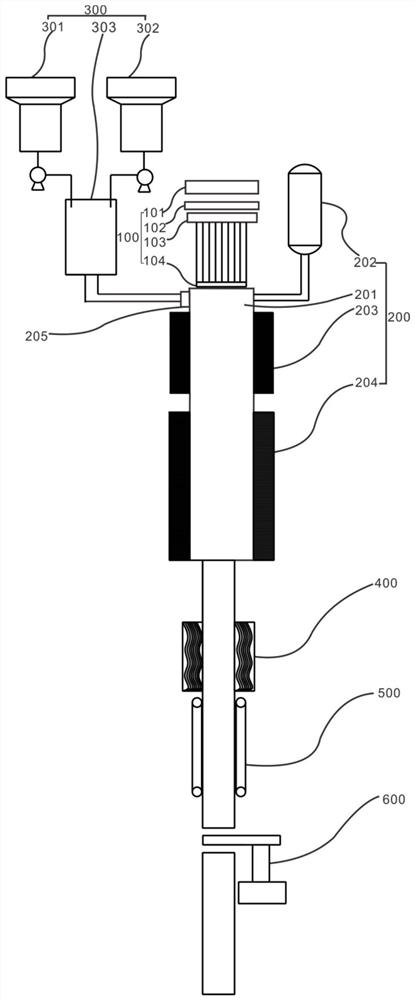
The invention discloses a continuous glass fiber reinforced polyurethane foam material forming process and system. The process comprises the following steps of forming a polyether polyol mixture, and respectively adding the polyether polyol mixture and isocyanate into two storage tanks; pulling loosened continuous glass fiber filaments through traction equipment to pass through a vertically-arranged forming mold; meanwhile, fully mixing two components of polyether polyol and isocyanate through a foaming machine, and injecting the mixture into a mold cavity in multiple directions; performing ultrasonic treatment to fully infiltrate the glass fiber filaments; foaming and curing the impregnated glass fibers under the action of microwaves; and cooling a shaping device and performing fixed-length cutting to obtain a continuous glass fiber reinforced polyurethane foam profile. The mold is vertically arranged, and a high-vacuum impregnation area, an ultrasonic infiltration device and a microwave curing device are arranged, so that uniform dispersion and arrangement of glass fibers in the inner cavity of the mold are facilitated; and the defects that the glass fibers droop in the mold, so that the density of the glass fibers at the lower part of the inner cavity is high, the density of the glass fibers at the upper part is low and pores are great are overcome.

Description

technical field [0001] The invention relates to the technical field of polyurethane composite material preparation, in particular to a continuous glass fiber reinforced polyurethane foam material molding process and system thereof. Background technique [0002] Polyurethane (PU) foaming materials are widely used in refrigerator insulation, shoe soles, building wall panels, mattresses, and automotive interior parts. [0003] At present, the pultrusion preparation technology using continuous fiber reinforced rigid polyurethane profiles has been used for the preparation of various load-bearing structural products, but due to the limitation of process conditions, the existing defects are as follows: [0004] First, high pressure is used to forcibly squeeze the polyurethane raw material between the reinforcing fibers, forcing the air that cannot be discharged to be squeezed between the reinforcing fibers and the resin, forming poor interfacial bonding, resulting in the mechanical...

Claims


Application Information

Patent Timeline
Patent Type & Authority Applications(China)
IPC IPC(8): B29C44/04B29C44/34B29C44/58C08G18/66C08G18/50C08G18/42C08K9/06C08K7/14C08J9/00
CPCB29C44/0423B29C44/34B29C44/3415B29C44/3403B29C44/3442B29C44/35B29C44/58C08G18/6674C08G18/4018C08G18/482C08G18/4238C08K7/14C08J9/009C08J2375/04
Inventor 董入贵刘烨管涌郑安呐陈璟
Owner 南京启华新材料科技有限公司
Learn More