
QPSK signal-oriented all-optical fast pattern matching method and system and application thereof

A pattern matching and signal technology, applied in the field of optical network security, can solve problems such as SOA cannot handle high-speed optical signals, SOA cannot exceed 10Gbps, lacks matching models for high-order modulation formats, etc., and achieves fast response to nonlinear effects. The effect of short nonlinear effect response time and strong anti-noise capability

Active Publication Date: 2021-10-08
BEIJING UNIV OF POSTS & TELECOMM
View PDF2 Cites 1 Cited by
  • Summary
  • Abstract
  • Description
  • Claims
  • Application Information

AI Technical Summary

Problems solved by technology

However, limited by the long carrier recovery time of SOA (about 100ps), it will cause the output pulse to broaden, and the working rate of a single SOA usually cannot exceed 10Gbps
The "Optical Signal Line Speed ​​Security Monitoring" project uses a push-pull Mach-Zehnder Interferometer (Semiconductor Optical Amplifier-based Mach-Zehnder Interferometer, SOA-MZI) structure matching model to achieve a maximum of 42.6Gbps using binary amplitude keying (On- OffKeying, OOK) modulation format optical signal matching, but cannot handle higher rate optical signals
[0009] (2) Lack of matching models suitable for high-order modulation formats
For optical signals using phase modulation, the amplitude of the input optical signal does not carry any information, and the XPM effect is no longer applicable at this time, so the matching model for optical signals using amplitude modulation cannot be applied to optical signals using phase modulation formats
At the same time, for optical signals using the QPSK modulation format, each symbol no longer contains only one bit of information "0" or "1". 1” variables for logic operations, and the existing logic gates cannot be used to realize the matching structure. In addition, there are problems such as SOA cannot handle high-speed optical signals.

Method used


Image

  • QPSK signal-oriented all-optical fast pattern matching method and system and application thereof
  • QPSK signal-oriented all-optical fast pattern matching method and system and application thereof
  • QPSK signal-oriented all-optical fast pattern matching method and system and application thereof

Examples


Embodiment 1

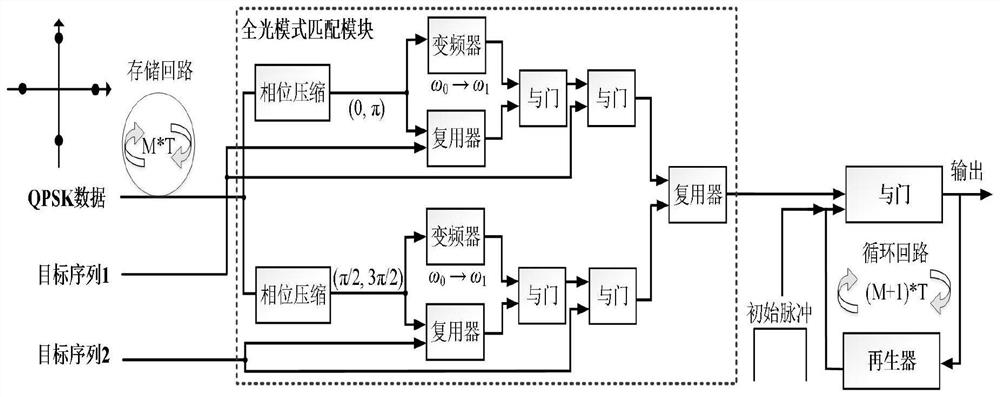
[0102] The simulation experiment is performed by the full-light fast mode matching system and method of the above specific embodiment.

[0103] The QPSK signal used includes four optional phase {0, π / 2, π, 3π / 2}, correspondingly encoded to {00, 01, 10, 11}, the corresponding decimal number is {0, 1, respectively. 2, 3}.

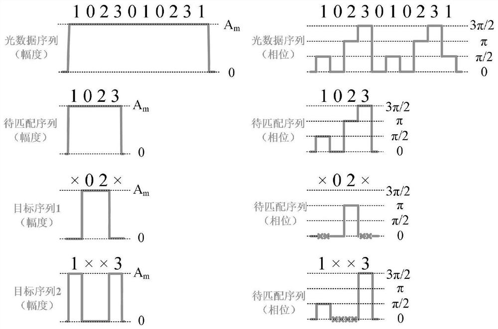
[0104] The input light data sequence is attached to the matching data figure 2 As shown, specifically:

[0105] The input light data sequence A = {1, 0, 2, 3, 0, 1, 0, 2, 3, 1}, the length m = 10, the magnitude is am.

[0106] The matching sequence b = {1, 0, 2, 3}, the length n = 4, the magnitude is also AM.

[0107] The standby sequence is divided into the target sequence 1 and the target sequence 2 according to the included symbols, so that only two symbols of the target sequence 1 and the target sequence 2 contain only two phase differences, specifically, where the target sequence 1 contains a phase 0 And the two symbols of π, {×, 0, 2, ×} (× indicates th...

Embodiment 2

[0125] In the condition and process of the first embodiment, the signal indication of each unit in the second cycle is shown. Figure 5 As shown, specific includes:

[0126] The input light data sequence A = {1, 0, 2, 3, 0, 1, 0, 2, 3, 1} is divided into two channels, filter the symbol of the phase 0 and π by the line, resulting in phase compression Sequence {×, 0, 2, ×, 0, ×, 0, 2, ×, ×}; filter the phase of π / 2 and 3π / 2 in the next circuit, resulting in a sequence after phase compression {1, × ×, 3, ×, 1, ×, ×, 3, 1}.

[0127] Select the standby sequence b = {0} during the second cycle, and its symbol duration is 10 * t, so the generated target sequence 1 is {0, 0, 0, 0, 0, 0, 0, 0, 0 , 0}, without any symbols in the generated target sequence 2.

[0128]The sequence after phase compression is divided into two channels, with one pass through the inverter, and otherwise enters the multiplexer together with the corresponding target sequence. For upright, the sequence after the f...

Embodiment 3

[0134] After the second cycle of Example 2, the third cycle is performed under the same system and conditions, and the signals of each unit are indicated. Image 6 As shown, specific includes:

[0135] The input light data sequence A = {1, 0, 2, 3, 0, 1, 0, 2, 3, 1} is divided into two channels, filter the symbol of the phase 0 and π by the line, resulting in phase compression Sequence {×, 0, 2, ×, 0, ×, 0, 2, ×, ×}; filter the phase of π / 2 and 3π / 2 in the next circuit, resulting in a sequence after phase compression {1, × ×, 3, ×, 1, ×, ×, 3, 1}. During the third cycle, the sequence B = {2} is served, and the symbol duration is 10 * t, so the generated target sequence 1 is {2, 2, 2, 2, 2, 2, 2, 2, 2. , 2}, there is no symbol in the generated target sequence 2.

[0136] The sequence after phase compression is divided into two channels, with one pass through the inverter, and otherwise enters the multiplexer together with the corresponding target sequence. For upright, the seque...


PUM


Abstract

The invention discloses a QPSK signal-oriented all-optical fast pattern matching method and system and application thereof, and the matching system or method divides a to-be-matched sequence into two paths containing different types of phase symbols, and carries out different compression on an optical data sequence composed of input QPSK signals by using phase compression processing, the data sequence is converted into two paths of data sequences only containing two phase symbols and one null symbol, and in the all-optical mode matching unit, each path only needs to identify two of the four phase symbols, so that the symbol processing process is simplified, the limitation of the original binary all-optical mode matching system is broken through, all-optical mode matching is extended to a higher-order modulation format, the processing efficiency and throughput of an all-optical mode matching system can be greatly improved, and mode recognition can be quickly and effectively completed.

Description

Technical field [0001] The present invention relates to the technical field of optical network security. Background technique [0002] At present, the flourishing of digital economy has become an important engine that promotes world economic growth, and the network is the cornerstone of digital world, building high-speed, reliable, and secure networks has always been my country's strategic plan. As the basic physical facility of various types of networks, the light network has the characteristics of large transmission capacity, more carrying business, and has a wide coverage area. It also has achieved rapid development, strongly supporting 5G, data centers, Internet of Things, empty-level integration. With the communications industry. Especially for 5G, due to the interconnection and data flow rate between the base station, the development of massive fiber optic cable needs, 5G development will greatly acne laser communication network construction and deployment. [0003] As the ...

Claims


Application Information

Patent Timeline
Patent Type & Authority Applications(China)
IPC IPC(8): H04Q11/00H04B10/548H04L27/20H04L29/06H04Q11/02
CPCH04Q11/0062H04B10/548H04L27/2096H04L63/02H04Q11/02
Inventor 李新黄善国唐颖石子成张路
Owner BEIJING UNIV OF POSTS & TELECOMM
Learn More