
All-optical fast pattern matching method and system for qpsk signal and its application

A pattern matching and signal technology, applied in the field of optical network security, can solve the problems that SOA cannot handle high-speed optical signals, lack of matching models for high-order modulation formats, SOA cannot exceed 10Gbps, etc., and achieve fast response to nonlinear effects, Short nonlinear effect response time, effect of equipment cost reduction

Active Publication Date: 2022-07-01
BEIJING UNIV OF POSTS & TELECOMM
View PDF2 Cites 0 Cited by
  • Summary
  • Abstract
  • Description
  • Claims
  • Application Information

AI Technical Summary

Problems solved by technology

However, limited by the long carrier recovery time of SOA (about 100ps), it will cause the output pulse to broaden, and the working rate of a single SOA usually cannot exceed 10Gbps
The "Optical Signal Line Speed ​​Security Monitoring" project uses a push-pull Mach-Zehnder Interferometer (Semiconductor Optical Amplifier-based Mach-Zehnder Interferometer, SOA-MZI) structure matching model to achieve a maximum of 42.6Gbps using binary amplitude keying (On- OffKeying, OOK) modulation format optical signal matching, but cannot handle higher rate optical signals
[0009] (2) Lack of matching models suitable for high-order modulation formats
For optical signals using phase modulation, the amplitude of the input optical signal does not carry any information, and the XPM effect is no longer applicable at this time, so the matching model for optical signals using amplitude modulation cannot be applied to optical signals using phase modulation formats
At the same time, for optical signals using the QPSK modulation format, each symbol no longer contains only one bit of information "0" or "1". 1” variables for logic operations, and the existing logic gates cannot be used to realize the matching structure. In addition, there are problems such as SOA cannot handle high-speed optical signals.

Method used


Image

  • All-optical fast pattern matching method and system for qpsk signal and its application
  • All-optical fast pattern matching method and system for qpsk signal and its application
  • All-optical fast pattern matching method and system for qpsk signal and its application

Examples


Embodiment 1

[0102] By carrying out the simulation experiment to the all-optical fast mode matching system and method of the above-mentioned specific embodiment, wherein:

[0103] The QPSK signal used includes four optional phases {0, π / 2, π, 3π / 2}, which are encoded as {00, 01, 10, 11}, and the corresponding decimal numbers are {0, 1 respectively , 2, 3}.

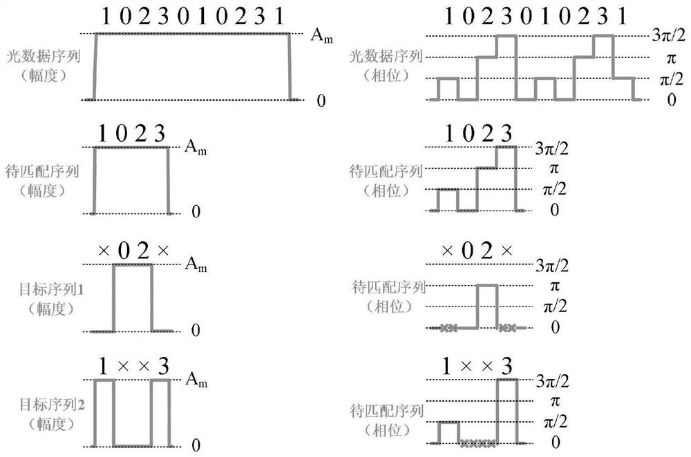
[0104] The input optical data sequence and the data to be matched are attached figure 2 shown, specifically:

[0105] The input optical data sequence A={1, 0, 2, 3, 0, 1, 0, 2, 3, 1}, its length M=10, and its amplitude is Am.

[0106] The to-be-matched sequence B={1, 0, 2, 3}, its length N=4, and its amplitude is also Am.

[0107] Divide the sequence to be matched into target sequence 1 and target sequence 2 according to the included symbols, so that target sequence 1 and target sequence 2 only contain two symbols with a phase difference of π. Specifically, target sequence 1 only contains phase 0. The two symbols of and π are {×, ...

Embodiment 2

[0125] Under the conditions and process of Embodiment 1, the signal representation of each unit in the second cycle of the matching system is as follows: Figure 5 shown, including:

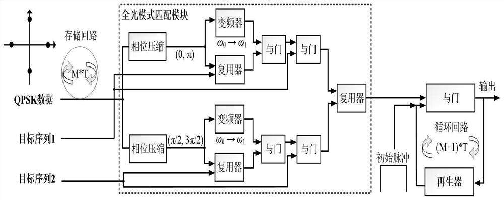
[0126] The input optical data sequence A={1, 0, 2, 3, 0, 1, 0, 2, 3, 1} is divided into two paths, and the symbols with phases 0 and π are filtered out on the upper path to obtain the phase-compressed Sequence {×, 0, 2, ×, 0, ×, 0, 2, ×, ×}; the symbols with phases π / 2 and 3π / 2 are filtered out in the lower path to obtain the phase-compressed sequence {1, × , ×, 3, ×, 1, ×, ×, 3, 1}.

[0127] Select the to-be-matched sequence B={0} during the second cycle, and its symbol duration is 10*T, so the generated target sequence 1 is {0, 0, 0, 0, 0, 0, 0, 0, 0 , 0}, and the resulting target sequence 2 does not contain any symbols.

[0128]Divide the sequence after phase compression into two paths, one of which goes through the frequency converter, and the other goes into the multiplexer together with ...

Embodiment 3

[0134] After the second cycle process in Example 2, the third cycle was carried out under the same system and conditions, and the signal representation of each unit was as follows: Image 6 shown, including:

[0135] The input optical data sequence A={1, 0, 2, 3, 0, 1, 0, 2, 3, 1} is divided into two paths, and the symbols with phases 0 and π are filtered out on the upper path to obtain the phase-compressed Sequence {×, 0, 2, ×, 0, ×, 0, 2, ×, ×}; the symbols with phases π / 2 and 3π / 2 are filtered out in the lower path to obtain the phase-compressed sequence {1, × , ×, 3, ×, 1, ×, ×, 3, 1}. During the third cycle, the sequence to be matched is B={2}, and its symbol duration is 10*T, so the generated target sequence 1 is {2, 2, 2, 2, 2, 2, 2, 2, 2 , 2}, and the resulting target sequence 2 does not contain any symbols.

[0136] Divide the sequence after phase compression into two paths, one of which goes through the frequency converter, and the other goes into the multiplexer ...


PUM


Abstract

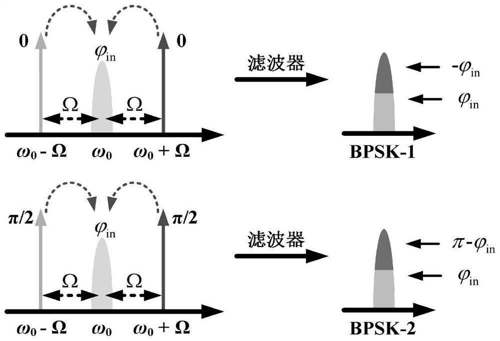
The invention discloses an all-optical fast pattern matching method and system for QPSK signals and its application, wherein the matching system or method divides a sequence to be matched into two paths containing different types of phase symbols, and uses phase compression processing to process the input signal. The optical data sequence composed of QPSK signals is compressed differently to transform it into two data sequences containing only two phase symbols and one null symbol. In the all-optical pattern matching unit, each channel only needs to identify four phase symbols. Two of them simplify the symbol processing process, break through the limitations of the original binary plenoptic mode matching system, not only extend the plenoptic mode matching to higher-order modulation formats, but also greatly improve the processing of the plenoptic mode matching system. Efficiency and throughput, pattern recognition is done quickly and efficiently.

Description

technical field [0001] The present invention relates to the technical field of optical network security. Background technique [0002] At present, the vigorous development of the digital economy has become an important engine for promoting world economic growth. The network is the cornerstone of building a digital world. Building a high-speed, reliable and secure network has always been my country's strategic plan. As the basic physical facilities of various types of networks, optical networks have the characteristics of large transmission capacity, many carrying services, and wide coverage. and the communications industry. Especially for 5G, the development of 5G will greatly stimulate the construction and deployment of optical communication networks due to the massive demand for fiber optic cables due to the interconnection between base stations and the growth of data traffic. [0003] As the physical link layer in the entire communication system, the optical network is ...

Claims


Application Information

Patent Timeline
Patent Type & Authority Patents(China)
IPC IPC(8): H04Q11/00H04B10/548H04L27/20H04L9/40H04Q11/02
CPCH04Q11/0062H04B10/548H04L27/2096H04L63/02H04Q11/02
Inventor 李新黄善国唐颖石子成张路
Owner BEIJING UNIV OF POSTS & TELECOMM
Learn More