Partitioned multi-stage circulating CO2 trapping and concentrating method based on mass transfer-reaction regulation and control

A technology of CO2 and reaction, which is applied in the field of CO2 capture and concentration based on mass transfer-reaction control, and can solve the problems of difficulty in improving capture efficiency, small adjustable range of system operating parameters, and low desorption energy consumption. , achieve the effects of high-efficiency suppression of secondary pollutants, reasonable temperature distribution in the tower, and reduced desorption energy consumption

Pending Publication Date: 2021-10-22
ZHEJIANG UNIV
View PDF6 Cites 8 Cited by
  • Summary
  • Abstract
  • Description
  • Claims
  • Application Information

AI Technical Summary

Problems solved by technology

However, this technology has the following disadvantages: the semi-lean liquid section does not absorb the absorption liquid to saturation before sending it to the desorption tower, and does not add circulating absorption liquid into the desorption tower, the flow rate is large, and the desorption energy consumption is large; the secondary pollutants such as aerosols are not treated control
However, this technology has the following disadvantages: the water washing tower and the trapping tower are set separately, the investment and operation cost is high, and the CO 2 It is difficult to further improve the capture efficiency, the energy consumption of desorption is large, the adjustable range of system operating parameters is small, and the adjustable performance is poor
[0005] In order to reduce the high cost of separate operation of the existing flue gas purification system and the carbon capture system, it is the most effective method to develop new absorbents with high absorption rate, large absorption capacity, and low desorption energy consumption. However, due to technical difficulties, a large amount of accumulation of experiments

Method used


Image

  • Partitioned multi-stage circulating CO2 trapping and concentrating method based on mass transfer-reaction regulation and control
  • Partitioned multi-stage circulating CO2 trapping and concentrating method based on mass transfer-reaction regulation and control
  • Partitioned multi-stage circulating CO2 trapping and concentrating method based on mass transfer-reaction regulation and control

Examples


Embodiment 1

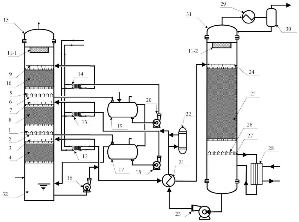
[0081] refer to figure 2 , a partitioned multistage cycle CO based on mass transfer-reaction regulation 2 Capture concentration method, using CO 2 capture concentration system, the CO 2 The capture and concentration system includes a multi-stage circulation absorption tower 15, a lean-rich liquid heat exchanger 21, a slurry cleaning device 22, a CO 2 Desorber 31 and CO 2 Concentration device.

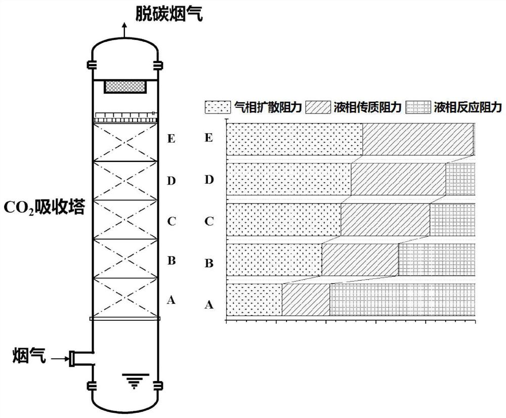
[0082] The multi-stage circulation absorption tower 15 includes a CO 2 Absorption system, secondary CO 2 Absorption system and three-stage water washing system; primary CO 2 Absorption system, secondary CO 2 The absorption system and the three-stage water washing system are connected in series from bottom to top, and the first mist eliminator 11-1 is installed at the top of the multi-stage circulation absorption tower 15 .

[0083] Flue gas enters primary CO 2 The absorption system passes through a section of packing layer 4, a section of nozzle 3, the first separator 2 and th...

Embodiment 2

[0106] refer to Figure 5 , a partitioned multistage cycle CO based on mass transfer-reaction regulation 2 Capture concentration method, using CO 2 capture concentration system, the CO 2 The capture and concentration system includes a multi-stage circulation absorption tower 15, a lean-rich liquid heat exchanger 21, a slurry cleaning device 22, a CO 2 Desorber 31 and CO 2 Concentration device.

[0107] The multi-stage circulating absorption tower 15 includes a Venturi type pre-washing section 33, a primary CO 2 Absorption system, secondary CO 2 Absorption system and three-stage water washing system. Level 1 CO 2 Absorption system, secondary CO 2 The absorption system and the three-stage water washing system are connected in series from bottom to top, and the first mist eliminator 11 is arranged on the top of the multi-stage circulation absorption tower 15 .

[0108] The Venturi type pre-washing section 33 is arranged at the front of the multi-stage circulation absorpt...

Embodiment 3

[0119] refer to Figure 6 , a partitioned multistage cycle CO based on mass transfer-reaction regulation 2 Capture concentration method, using CO 2 capture concentration system, the CO 2 The capture and concentration system includes a multi-stage circulation absorption tower 15, a lean-rich liquid heat exchanger 21, a slurry cleaning device 22, a CO 2 Desorber 31 and CO 2 Concentration device.

[0120] The multi-stage circulating absorption tower 15 includes a Venturi type pre-washing section 33, a primary CO 2 Absorption system, secondary CO 2 Absorption system, tertiary CO 2 Absorption system and four-stage water washing system. Level 1 CO 2 Absorption system, secondary CO 2 Absorption system, tertiary CO 2 The absorption system and the four-stage water washing system are connected in series from bottom to top, and the first mist eliminator 11-1 is installed on the top of the multi-stage circulation absorption tower 15 .

[0121] The Venturi type pre-washing secti...


PUM

PropertyMeasurementUnit
thermal efficiencyaaaaaaaaaa

Abstract

The invention relates to a partitioned multi-stage circulating CO2 trapping and concentrating method based on mass transfer-reaction regulation and control. The method adopts multi-element means such as multi-stage cycle absorption, intelligent multi-factor regulation, pre-washing cooling, inter-stage cooling, post-stage water washing, slurry cleaning, cooling water waste heat utilization, small-particle-size high-density spraying and the like. The method takes low cost, low energy consumption, stability and high efficiency as optimization targets, the generation of secondary pollutants is effectively inhibited while CO2 is efficiently trapped, and high-efficiency trapping, low-energy-consumption desorption and high-purity concentration of CO2 are realized. Aerosol removal is sequentially carried out from top to bottom through multi-stage circulation, the carbon capture efficiency is improved, the absorption rate and rich solution concentration are maintained, and the carbon emission reduction cost is reduced.

Description

technical field [0001] The invention belongs to the technical field of air pollution control and carbon emission reduction, and specifically relates to a partitioned multi-stage cycle CO2 based on mass transfer-reaction regulation. 2 Capture concentration method. Background technique [0002] Carbon dioxide is one of the main components of the greenhouse gas that contributes to global warming. Carbon dioxide is mainly derived from the burning of fossil fuels such as coal, oil and natural gas. However, coal-fired units and industrial production have a large amount of carbon emissions, and the overall smoke exhaust properties are as follows: a large amount of flue gas, low carbon dioxide content and low partial pressure in the flue gas, resulting in high cost of carbon dioxide capture; flue gas contains SO 2 , SO 3 , NO x , heavy metals and soot and other impurities, easy to produce secondary pollutants, for CO 2 The capture process has certain negative effects. At presen...

Claims


Application Information

Patent Timeline
Patent Type & Authority Applications(China)
IPC IPC(8): B01D53/14B01D53/75B01D53/78B01D53/96B01D53/50B01D53/54B01D53/60B01D53/62B01D53/68C01B32/50
CPCB01D53/1475B01D53/1406B01D53/1425B01D53/1418B01D53/1412B01D53/78B01D53/75B01D53/50B01D53/54B01D53/60B01D53/68B01D53/96B01D53/62C01B32/50B01D2258/0283Y02A50/2351Y02C20/40Y02P20/129Y02P20/151B01D2252/204B01D2252/602B01D53/145B01D53/1493B01D53/185B01D2252/103B01D2257/504C01B17/806
Inventor 高翔郑成航刘昶周灿张悠赵中阳张淼张杨李钦武张涌新翁卫国吴卫红张霄杨洋姚龙超
Owner ZHEJIANG UNIV
Why Eureka
Try Eureka