A kind of hose manufacturing method and probe hose
A manufacturing method and a hose technology, applied in the field of hoses, can solve problems such as affecting the efficiency of doctors' use, and achieve the effect of improving detection efficiency
- Summary
- Abstract
- Description
- Claims
- Application Information
AI Technical Summary
Problems solved by technology
Method used
Image
Examples
Embodiment 1
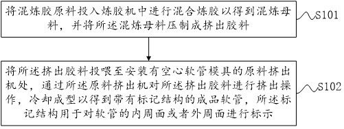
[0060] see figure 1 , figure 1 It is a schematic flow chart of the hose manufacturing method disclosed in the embodiment of the present invention. like figure 1 As shown, the hose-based fabrication method includes the following steps:
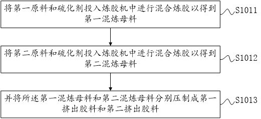
[0061] S101: drop the mixing rubber raw material into a rubber mixing machine and carry out mixing and mixing to obtain a mixing master batch, and press the mixing master batch into an extrusion rubber material;
[0062] During the implementation, the plastic raw material can be directly used as the raw material of the mixed rubber, and if the thermoplastic material is used, it can be formed by heating and cooling; the production is more convenient. In specific implementation, not only plastic raw materials, but also rubber raw materials can be used. When using rubber raw materials for thermosetting, vulcanization treatment is required.
[0063] After the vulcanization, the following steps need to be performed after step S102: put the fini...
Embodiment 2
[0102] Figure 4 is a schematic structural diagram of the probe hose disclosed in the embodiment of the present invention, Figure 5 It is a schematic diagram of the exploded structure of the probe hose disclosed in the embodiment of the present invention, such as Figure 4 and Figure 5 As shown, a second aspect of the embodiment of the present invention discloses a probe hose, comprising:
[0103] a tubular body 1 for defining a through hole, an inner peripheral surface 12 and an outer peripheral surface 11;
[0104] The marking structure 2 is provided in the hose body, and the marking structure 2 is used to mark the inner peripheral surface 12 or the outer peripheral surface 11 .
[0105] In the embodiment of the present invention, the main purpose of the marking structure 2 is to determine the inner and outer peripheral surfaces 11 of the tubular body 1; when determining the specific structure, an object with a regular shape or an object with an irregular shape can be u...
Embodiment 3
[0115] see Figure 8 , Figure 8It is a schematic flowchart of a method for automatically adjusting an image disclosed in an embodiment of the present invention. Wherein, the execution body of the method described in the embodiments of the present invention is an execution body composed of software or / and hardware, and the execution body can receive relevant information in a wired or / or wireless manner, and can send certain instructions. Of course, it may also have certain processing functions and storage functions. The executive body can control multiple devices, such as a remote physical server or cloud server and related software, or can be a local host or server and related software that perform related operations on a device located somewhere. In some scenarios, multiple storage devices can also be controlled, and the storage devices can be placed in the same place as the device or in a different place. like Figure 8 As shown, the method based on automatic image adju...
PUM
 Abstract
Description
Claims
Application Information
 - R&D
- Intellectual Property
- Life Sciences
- Materials
- Tech Scout
- Unparalleled Data Quality
- Higher Quality Content
- 60% Fewer Hallucinations
Browse by: Latest US Patents, China's latest patents, Technical Efficacy Thesaurus, Application Domain, Technology Topic, Popular Technical Reports.
© 2025 PatSnap. All rights reserved.Legal|Privacy policy|Modern Slavery Act Transparency Statement|Sitemap|About US| Contact US: help@patsnap.com


