
Alcohol vapor waste heat recycling process

A technology of waste heat recovery and juice vapor, applied in evaporation, heat exchanger, distillation and separation, etc., can solve the problems of low energy utilization rate, high energy consumption, and large energy waste, so as to improve utilization rate, reduce pollution, and increase heat energy The effect of utilization

Pending Publication Date: 2021-12-03
成都鸿展慧智科技有限公司
View PDF14 Cites 0 Cited by
  • Summary
  • Abstract
  • Description
  • Claims
  • Application Information

AI Technical Summary

Problems solved by technology

[0005] The purpose of the present invention is that the alcohol production equipment in the prior art has the problems of low energy utilization rate, high energy consumption, and large energy waste. This application proposes a recovery and utilization process for the waste heat of alcohol evaporation juice vapor

Method used


Image

  • Alcohol vapor waste heat recycling process

Examples


Embodiment 1

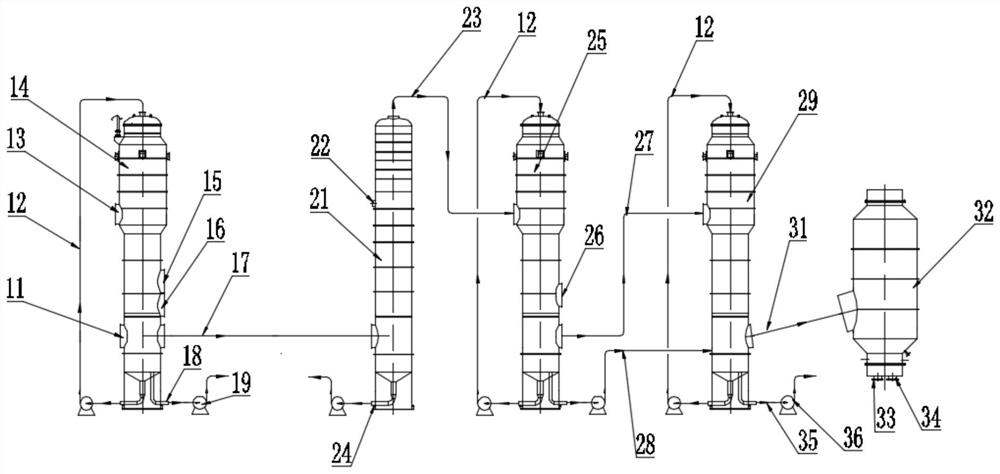
[0043] Such as figure 1 As shown, this embodiment is a process for recovering and utilizing waste heat from alcohol evaporated juice vapor, which specifically includes the following steps:

[0044] Step 1: Pass the 95°C steam from the dryer and the 80°C clear liquid from the decanter centrifuge into the single-effect falling film generator;

[0045] Step 2: The juice vapor produced in the single-effect falling film generator enters the distillation section crude tower 21 through the first juice vapor pipe 17 connected between the single-effect falling film evaporator 14 and the distillation section rough tower 21 to be the distillation section rough tower 21. The mash in the tower 21 supplies heat, carries out heat transfer, produces wine vapor;

[0046]Step 3: The wine vapor generated in the crude tower 21 of the distillation section enters the No. 1 falling film generator through the wine vapor pipe 23 to provide heat for the materials in the No. 1 falling film generator, a...

Embodiment 2

[0055] Such as figure 1 As shown, the difference from Example 1 is that the concentration of the concentrated solution discharged from the single-effect falling film generator in this example is controlled to be 7%.

Embodiment 3

[0057] Such as figure 1 As shown, based on Example 1 and Example 2, the single-effect falling film generator, No. 1 falling film generator, and No. 2 falling film generator of this example are all connected with a material circulation structure.

[0058] Wherein, the material circulation structure comprises the material circulation pipe 12 connected between the bottom and the top of the single-effect falling film evaporator 14, the No. 1 falling film evaporator 25, and the No. 2 falling film evaporator 29, and the material circulation pipe 12 is connected with Evaporation circulation pump.

[0059] The single-effect falling film evaporator 14, the No. 1 falling film evaporator 25, and the No. 2 falling film evaporator 29 are all connected to the circulation structure, and the power provided by the evaporation circulation pump connected to the material circulation pipe 12 makes the materials flow in the single-effect respectively. Efficient falling film evaporator 14, No. 1 fa...


PUM


Abstract

The invention discloses an alcohol vapor waste heat recycling process, relates to the technical field of waste heat recycling treatment equipment, and solves the problems of low energy utilization rate, high energy consumption and large energy waste of alcohol production equipment in the prior art. The process specifically comprises the following steps: vapor of 95 DEG C and clear liquid of 80 DEG C are introduced into a single-effect falling film generator, and generated vapor is introduced into a distillation section crude tower to supply heat to mash in the distillation section crude tower so as to generate alcohol vapor; the generated alcohol vapor enters a first falling film generator; vapor generated in the first falling film generator enters a second falling film generator; meanwhile, concentrated liquid generated in the first falling film generator enters the second falling film generator together to supply heat to materials in the second falling film generator; and vapor generated in the second falling film generator enters a condenser for cooling treatment. According to the process, heat contained in vapor is fully utilized, the utilization rate of heat energy in a feed workshop is increased, and energy waste is reduced.

Description

technical field [0001] The invention relates to the technical field of waste heat recovery and utilization treatment equipment, and more specifically relates to the technical field of recovery and utilization of waste heat from alcohol evaporated juice vapor. Background technique [0002] Alcohol production is developed on the basis of brewing. my country's alcohol production methods include synthesis and fermentation, with fermentation as the main method. From the perspective of technology, well-known sugar cane, corn, cassava, grains, etc. contain sugar Plants, starchy and cellulose crops can be used as raw materials to produce alcohol through pretreatment, fermentation and distillation. [0003] In order to further improve the production level of alcohol, engineers and technicians from all over the world are researching new equipment and process systems, such as solidified cell alcohol fermentation, high temperature resistant active dry yeast fermentation and other new fer...

Claims


Application Information

Patent Timeline
IPC IPC(8): B01D3/00B01D1/22F28D21/00
CPCB01D3/003B01D1/22F28D21/0001Y02P70/10
Inventor 杨聪
Owner 成都鸿展慧智科技有限公司
Learn More