Method for preparing complex thin-wall component through laser metal deposition and follow-up rolling
A thin-walled component and complex technology, applied in metal rolling, metal rolling, metal processing equipment, etc., can solve problems such as poor surface quality, secondary deformation, and reduced reliability, and achieve improved density and uniform structure and performance Sex, to avoid the effect of secondary deformation
- Summary
- Abstract
- Description
- Claims
- Application Information
AI Technical Summary
Problems solved by technology
Method used
Image

Examples
Embodiment 1
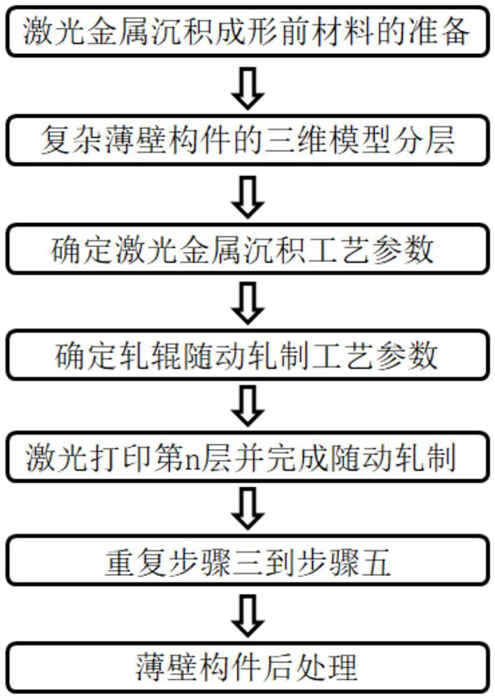
[0031] Example 1: Combining figure 1 ,figure 2, image 3 , Figure 4 , Fig. 5 illustrate, the method that the present invention proposes adopts laser metal deposition and follow-up rolling to prepare complex thin-walled member, and this method is to carry out according to the following steps:
[0032] Step 1. Preparation of materials before laser metal deposition forming. Select the type of metal powder according to the material, structure and performance requirements of the formed component, and select the metal substrate according to the material type selected for the component. The metal powder needs to be placed in a vacuum drying furnace to remove moisture before use. In order to make the component and the substrate Forming a good metallurgical bond requires mechanical grinding and cleaning of the metal substrate.
[0033] Step 2, layering the 3D model of the complex thin-walled components. Establish the CAD geometric model of the component according to the three-dime...
Embodiment 2
[0040] Example 2: In conjunction with Figure 2, in step 1, the selected metal powder is GH3536 nickel-based superalloy powder prepared by a vacuum atomization process with a particle size distribution range of 53-106um. The metal substrate is 304 stainless steel, and the metal Before use, the powder was heat-treated in a vacuum drying oven at 120° C. for 3 hours to remove internal moisture, and the other steps were the same as in Example 1.
[0041] The beneficial effect of this embodiment is: the GH3536 nickel-based superalloy has a high alloy content and can withstand a variety of severe corrosive environments. Even in severe corrosive environments, the combination of nickel and chromium can resist oxidation reactions, and the presence of molybdenum These alloys are resistant to pitting and crevice corrosion; in addition, the 304 stainless steel substrate can form a good metallurgical bond with the formed GH3536 thin-walled components, avoiding the cracking defects of both. ...
Embodiment 3
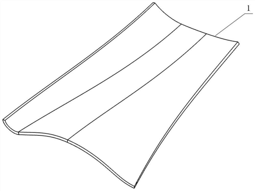
[0042] Example 3: Binding image 3 Note that in steps 3 to 5, when preparing thin-walled plate-shaped components with complex surfaces, the scheme of synchronous reciprocating motion of the laser head and the roll is adopted. During the reciprocating motion, the deflection angle of the roll needs to be adjusted to keep the roll in line contact with the deposition area. , the other steps are the same as in Example 1.
[0043] The beneficial effect of this embodiment is: when forming complex curved thin-walled plate-like components, the laser head and the roller move back and forth synchronously, and the roller performs follow-up rolling on the deposition area completed by laser printing. Stress causes deformation, which makes the laser beam unable to act on the end face of the component, so that the continuous printing of the component cannot be completed, and the complex and special-shaped thin-walled plate with variable wall thickness and special requirements can be prepared ...
PUM
| Property | Measurement | Unit |
|---|---|---|
| Thickness | aaaaa | aaaaa |
Abstract
Description
Claims
Application Information
 - R&D
- Intellectual Property
- Life Sciences
- Materials
- Tech Scout
- Unparalleled Data Quality
- Higher Quality Content
- 60% Fewer Hallucinations
Browse by: Latest US Patents, China's latest patents, Technical Efficacy Thesaurus, Application Domain, Technology Topic, Popular Technical Reports.
© 2025 PatSnap. All rights reserved.Legal|Privacy policy|Modern Slavery Act Transparency Statement|Sitemap|About US| Contact US: help@patsnap.com