
3D printing nozzle based on ultrasonic micro forging and printing method

A 3D printing and printing head technology, applied in the field of additive manufacturing, can solve the problems of low surface activity of fiber-reinforced phase materials, weak strength of FDM molded parts, and reduced quality of printed parts, so as to improve the quality and accuracy of printing surfaces and improve the melting point. Bulk viscosity and fluidity, the effect of improving print bond strength

Active Publication Date: 2021-12-03
CHENGDU AIRCRAFT INDUSTRY GROUP
View PDF11 Cites 3 Cited by
  • Summary
  • Abstract
  • Description
  • Claims
  • Application Information

AI Technical Summary

Problems solved by technology

[0003] Although FDM forming has the advantages of simple structure, convenient operation, and low printing cost, there are still many problems such as insufficient strength of formed parts, poor forming surface quality, low forming accuracy, slow processing speed, and poor forming interface of particle or fiber reinforced composite materials. shortcoming
Among them, the weak strength of FDM formed parts is also one of the main limiting factors restricting the further development and application of FDM technology.
The strength of the printed part is mainly determined by the printing process and the forming material itself, but it is also affected by the FDM forming method itself
The principle of FDM is to divide the solid model into several layers and print each layer. Layers and layers, lines and lines are connected by re-solidification after melting, and this re-solidification connection method after melting is very vulnerable. Influenced by factors such as printing temperature, printing speed, material properties, and printing line width, it is very easy to cause problems such as small gaps or weak bonding between layers and lines and lines during the printing process, which eventually leads to insufficient printing connection strength. As a result, cracks and fractures occur in the printed parts during post-processing or stress
On the other hand, the weak interfacial bonding strength of fiber-reinforced PEEK-based composites is one of the main limiting factors restricting its industrial application in FDM forming
The surface activity of the fiber-reinforced phase material is low, and the bonding strength with the matrix material is weak. In traditional thermoforming, due to the pressure-induced effect, its bonding strength can be controlled. It is easy to cause poor interface bonding strength, resulting in a decline in the quality of printed parts, so it is more difficult to form high-performance reinforced PEEK-based composite materials with high quality fractions
[0004] In response to these problems, many scholars and technicians mainly use methods such as printing material selection, material modification, and printing process optimization, but there is still no good overall solution.

Method used


Image

  • 3D printing nozzle based on ultrasonic micro forging and printing method
  • 3D printing nozzle based on ultrasonic micro forging and printing method

Examples


Embodiment 1

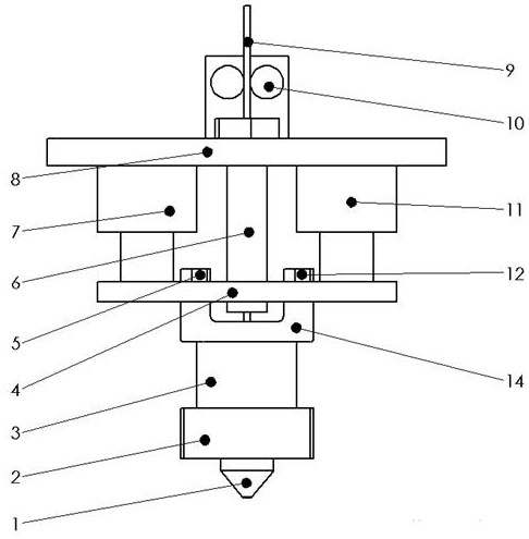
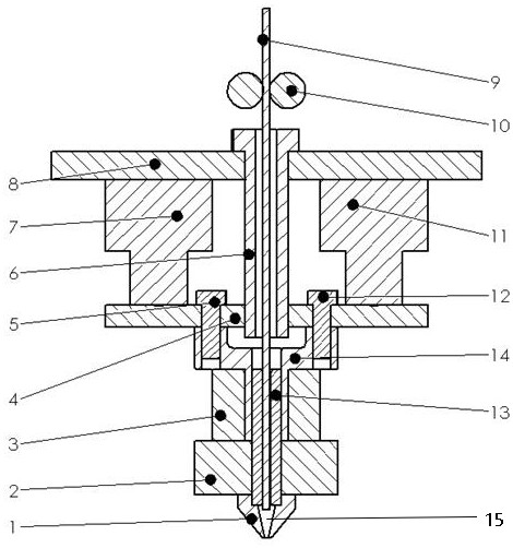
[0031] A 3D printing nozzle based on ultrasonic micro-forging, including a printing head 1 with a melting cavity 15 inside, the upper part of the printing head 1 is connected to the lower end of the melting throat 13 by threads, and the outer part of the lower end of the melting throat 13 is connected to the printing heat source 2 by interference Fitting connection, the upper end of the melting throat 13 is connected to the cooling device 3, the top of the melting throat 13 is connected with the middle hole at the bottom of the adapter bracket 14 with an interference fit, the top of the adapter bracket 14 is connected with the connecting plate 4, and the middle hole of the connecting plate 4 and The lower end of the threaded pipe 6 is connected, and the upper end of the threaded pipe 6 is connected to the two-dimensional module connecting frame 8, and the first ultrasonic vibration transducer 7 and the second ultrasonic vibration transducer are connected between the two-dimensio...

Embodiment 2

[0038]A method for printing a 3D printing nozzle based on ultrasonic micro-forging, comprising the following steps:

[0039] The first step is to install the 3D printing nozzle based on ultrasonic micro-forging on the 3D printer, first turn on the cooling device 3 and the printing heat source 2 in sequence, and wait until the temperature of the melting throat 13, the printing head 1 and the melting chamber 15 reach the set working melting temperature After the temperature is reached, the wire material 9 is transported into the melting cavity 15 inside the print head 1 through the wire feeder 10, and then the first ultrasonic vibration transducer 7 and the second ultrasonic vibration transducer 11 are turned on, and the high-frequency vibration force field It is transmitted to the print head 1 and the melting cavity 15 through the connecting plate 4, the threaded pipe 6, the adapter bracket 14, and the melting throat 13 in turn. The printer control system controls the two-dimens...

Embodiment 3

[0045] Such as figure 1 and figure 2 As shown, a 3D printing nozzle based on ultrasonic micro-forging includes a printing head 1 with a melting cavity 15 inside. Relying on the interference fit connection, the upper end of the melting throat 13 is connected to the cooling device 3 outside, the top of the melting throat 13 is connected to the middle hole at the bottom of the adapter bracket 14 with an interference fit, and the top of the adapter bracket 14 is connected to the connecting plate 4 through the first screw 5 1. The second screw 12 is connected, the middle hole of the connecting plate 4 is connected with the lower end of the threaded pipe 6, the outer part of the upper end of the threaded pipe 6 is connected with the two-dimensional module connecting frame 8, and the first ultrasonic wave is connected between the two-dimensional module connecting frame 8 and the connecting plate 4. The vibration transducer 7 and the second ultrasonic vibration transducer 11, a wire...


PUM


Abstract

The invention relates to the field of laser line width measurement, and particularly relates to a 3D printing nozzle based on ultrasonic micro forging and a printing method. The 3D printing nozzle comprises a printing head internally provided with a melting cavity; the upper portion of the printing head is connected with the lower end of a melting throat pipe; the outer portion of the lower end of the melting throat pipe is connected with a printing heat source; the outer portion of the upper end of the melting throat pipe is connected with a cooling device; the top end of the melting throat pipe is connected with the bottom of a through connection support; the top of the through connection support is connected with a connecting plate; the connecting plate is connected with the lower end of a threaded pipe; the outer portion of the upper end of the threaded pipe is connected with a two-dimensional module connecting frame; a first ultrasonic vibration transducer and a second ultrasonic vibration transducer are connected between the two-dimensional module connecting frame and the connecting plate; and a wire feeder is arranged above the top end of the threaded pipe and conveys wires to the threaded pipe, the melting throat pipe and the melting cavity in sequence. According to the 3D printing nozzle based on ultrasonic micro forging and the printing method, the micro forging function in the printing process is achieved, the melt fluidity is improved, the melt pressure in a melting wall is increased, and the FDM printing strength, the printing speed and the printing precision are improved.

Description

technical field [0001] The invention belongs to the technical field of additive manufacturing, and in particular relates to a 3D printing nozzle based on ultrasonic micro-forging and a printing method. Background technique [0002] Fused deposition modeling (FDM) technology utilizes the hot-melt and cohesive properties of thermoplastic materials. Under the control of the computer, the filament is heated and melted by the heat source, and the molten material is sprayed on the printing platform through the fine nozzle at the bottom of the nozzle Extrude on top, and stack and superimpose layers to finally form the desired product or model. Due to the simple structure of the printer equipment, convenient operation, fast forming speed, and rich types of materials, and because it does not need to use a laser system, the maintenance and operation costs are low. FDM 3D printing technology has been increasingly used in medical and health care, aerospace, Automobile industry, educati...

Claims


Application Information

Patent Timeline
Patent Type & Authority Applications(China)
IPC IPC(8): B29C64/209B29C64/118B29C64/307B33Y10/00B33Y30/00B33Y40/00
CPCB29C64/209B29C64/118B29C64/307B33Y10/00B33Y30/00B33Y40/00
Inventor 齐世文杨东门向南荣鹏李晓军
Owner CHENGDU AIRCRAFT INDUSTRY GROUP
Learn More