Method and production device for extracting ultra-pure helium from helium-containing natural gas at normal temperature in gradient manner

A natural gas and helium technology, applied in chemical instruments and methods, climate sustainability, inert gas compounds, etc., can solve problems such as narrow application range, high production energy consumption, and low yield of helium products

Pending Publication Date: 2021-12-03
李保军
View PDF0 Cites 1 Cited by
  • Summary
  • Abstract
  • Description
  • Claims
  • Application Information

AI Technical Summary

Problems solved by technology

[0003] The relevant patents related to helium recovery or helium production that have been found so far mainly include two types, one is the purification and separation of process tail gas; the other is helium extraction from natural gas or air separation tail gas. Combination of cold or cryogenic and other technologies, this type of method can obtain high-purity helium products, but the production energy consumption is high, and its economy cannot meet the requirements when operating without by-production of LNG; there are also some It is a simple membrane method or pressure swing/temperature swing adsorption technology, which can obtain helium products with a certain purity, but the application rang

Method used


Image

  • Method and production device for extracting ultra-pure helium from helium-containing natural gas at normal temperature in gradient manner
  • Method and production device for extracting ultra-pure helium from helium-containing natural gas at normal temperature in gradient manner
  • Method and production device for extracting ultra-pure helium from helium-containing natural gas at normal temperature in gradient manner

Examples


Embodiment 1

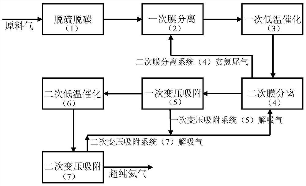
[0021] Please refer to the attached figure 1 . This figure embodies the main equipment of the present invention and its interconnection.

[0022] Helium-containing raw material gas 1 enters the primary membrane separation system (2) after being treated by the desulfurization and decarbonization system (1). The operating pressure of the membrane module is 2.90MPag, and the operating temperature is 60°C. After being treated by the gas separation membrane, the helium-removed tail gas is sent out of the boundary, and the concentrated hydrogen-containing raw material gas is sent to the primary low-temperature catalytic system (3). The dehydrogenation raw material gas after dehydrogenation treatment by the primary low-temperature catalytic system is sent to the secondary membrane separation system (4). The operating pressure of the membrane module is 2.90MPag, and the operating temperature is 60°C. After being treated by the gas separation membrane, the helium-removed tail gas r...

Embodiment 2

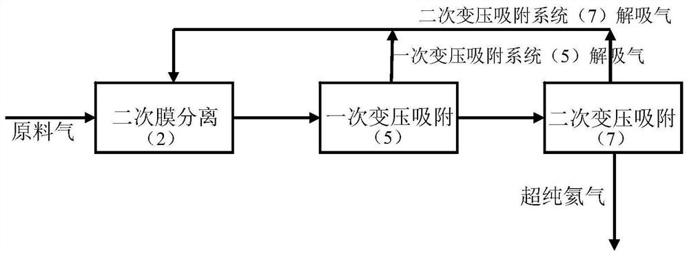
[0028] Please refer to the attached figure 2 . This figure embodies the main equipment of the present invention and its interconnection.

[0029] The helium-containing raw material gas 2 directly enters the secondary membrane separation system (4). The operating pressure of the membrane module is 6.90MPag, and the operating temperature is 70°C. After being treated by the gas separation membrane, the helium-removed tail gas is sent outside the boundary, and the raw material gas with high helium content is sent to the primary pressure swing adsorption system (5). The operating pressure of the pressure swing adsorption tower is 2.9MPag, and the operating temperature is 30°C. After treatment, the desorbed gas and the desorbed gas of the secondary pressure swing adsorption system (7) return to the secondary membrane separation system (4), and the helium concentration after the extraction reaches 99.9%, and enters the secondary pressure swing adsorption system (7 ), the operatin...

Embodiment 3

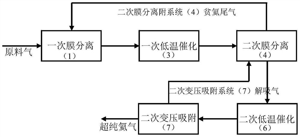
[0035] Please refer to the attached image 3 . This figure embodies the main equipment of the present invention and its interconnection.

[0036] The raw material gas containing helium enters the primary membrane separation system (2) directly. The operating pressure of the membrane module is 2.90MPag, and the operating temperature is 70°C. After being treated by the gas separation membrane, the helium-removed tail gas is sent out of the boundary, and the concentrated hydrogen-containing raw material gas is sent to the primary low-temperature catalytic system (3). The dehydrogenation raw material gas after the dehydrogenation treatment in the primary low-temperature catalytic system (3) is sent to the secondary membrane separation system (4). The operating pressure of the membrane module is 2.90 MPag, and the operating temperature is 70 °C. After being treated by the gas separation membrane, the helium-depleted tail gas is returned to the primary membrane separation system...


PUM


Abstract

The invention discloses a method and a production device for extracting ultra-pure helium from helium-containing natural gas at normal temperature in a gradient manner, and belongs to the technical field of petrochemical engineering. Membrane separation, pressure swing adsorption, low-temperature catalysis and desulfurization and decarburization technologies are integrated according to the treatment capacity in a cascade mode, when helium in helium-containing natural gas/geothermal water dissolved gas is purified, the desulfurization and decarburization technologies, the membrane separation technologies, the pressure swing adsorption technologies and the low-temperature catalysis technologies are placed at proper separation positions according to the optimal separation interval of the separation technologies, and a multi-technology cascade integration process is formed. Helium contained in helium-containing natural gas/geothermal water dissolved gas is purified step by step through the process, and finally helium with the volume fraction not lower than 99.9999% is obtained. According to the process, through cascade combination and mutual cooperation of multiple technologies, the development bottleneck of a single separation technology is successfully broken, the helium yield is greatly improved, the investment and energy consumption in the process of extracting helium from helium-containing natural gas/geothermal water dissolved gas are reduced, the service life of a separation system is prolonged, and available helium resources are broadened.

Description

technical field [0001] The invention belongs to the field of petrochemical technology. The present invention integrates membrane separation, pressure swing adsorption, low-temperature catalysis, and desulfurization and decarburization technologies. When purifying helium in raw material gas, desulfurization and decarburization, membrane separation, Pressure swing adsorption and low-temperature catalytic technology are placed in suitable separation positions to form a multi-technical cascade integration process. The helium-containing raw material gas is purified in steps, and finally a qualified ultra-pure helium product is obtained. In addition to the production of helium and natural gas, the present invention can also produce by-products such as carbon dioxide or nitrogen with relatively high purity according to the raw material conditions. Background technique [0002] So far, helium mainly comes from helium-containing natural gas. Therefore, the technology of extracting ...

Claims


Application Information

Patent Timeline
IPC IPC(8): C01B23/00
CPCC01B23/0094Y02P20/10
Inventor 李保军范瑛琦贺高红盖丽梅
Owner 李保军
Why Eureka
Try Eureka