Mode controller from multi-core optical fiber to annular core optical fiber

A mode controller and multi-core optical fiber technology, applied in multi-core optical fiber, clad optical fiber, optical waveguide light guide, etc., can solve the problems of small mode conversion range, mode crosstalk, and increased beam loss, and achieve high mode conversion efficiency. The effect of high device stability and reversible mode conversion

Pending Publication Date: 2021-12-31
GUILIN UNIV OF ELECTRONIC TECH
View PDF6 Cites 0 Cited by
  • Summary
  • Abstract
  • Description
  • Claims
  • Application Information

AI Technical Summary

Problems solved by technology

Patent No. CN200810021652.8 uses a dual-core photonic crystal fiber to achieve mode conversion between LP01 mode and LP02 mode. The dual-core photonic crystal fiber is composed of air holes and two cores, and the two cores have different diameters. Heterogeneous core, small core transmits LP01 mode, large core transmits LP02 mode, in this fiber, the two modes will be periodically coupled at a wavelength of 1.55um, and the length of the maximum coupling value can be selected to complete LP01 The mode conversion between LP02 mode and LP02 mode has the advantages of low loss and high conversion efficiency, but it has strict requirements on the wavelength of transmitted light, and the mode conversion range is small, so it can only be converted between the two modes
The patent No. CN202010787190.1 mentions the use of long-period gratings to achieve mode conversion. This patent uses carbon dioxide lasers to write long-period gratings on few-mode fibers to convert LP01 modes into high-order LP11 modes. Multiple The long-period grating cascading method converts the LP01 mode into the LP11 mode, and then converts the LP11 mode into the LP21 mode, so as to realize the conversion from the low-order mode to the higher-order mode, but the purity of the conversion mode is not high, and it is necessary to add a filter The mode filter filters out the higher-order modes in the beam, so the loss of the beam in this scheme will increase with the number of mode transitions
[0004] From the existing technology, most of the mode excitation and transmission are based on few-mode fibers and multi-mode fibers, but there has been no effective way to excite high-order transmission modes for ring-core fibers. The main reason is that ring-core fibers The waveguide structure is difficult to excite high-order modes. In addition, photon orbital angular momentum fiber communication is one of the development trends of large-capacity communication research. Traditional single-mode fiber and multimode fiber will cause mode crosstalk and cannot transmit photon orbital angular momentum over long distances. model

Method used


Image

  • Mode controller from multi-core optical fiber to annular core optical fiber
  • Mode controller from multi-core optical fiber to annular core optical fiber
  • Mode controller from multi-core optical fiber to annular core optical fiber

Examples


Embodiment 1

[0031]Example 1: Integrated quad-fiber to ring-core fiber mode controller with phase modulation via graphene.

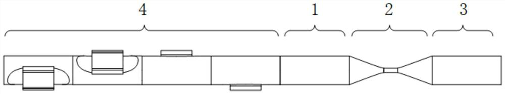
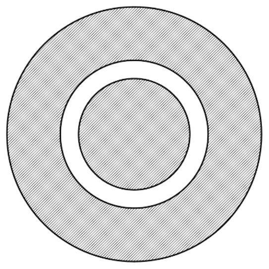
[0032] figure 1 The schematic structural diagram of the mode controller from the integrated four-core fiber to the ring-core fiber is shown, which is composed of four-core fiber 1, mode field conversion area 2, ring-core fiber 3 and phase modulation module 4, wherein the mode field conversion Area Figure 4 As shown, the four-core fiber 1 and the ring-core fiber 3 are fused after being tapered. The design of the tapered area can increase the wavelength bandwidth and improve the tolerance rate of fiber matching. After the ring-core fiber is tapered It needs to match the core of the quadruple fiber, and the taper of the ring-core fiber is slightly longer than the taper of the quadruple fiber. The geometric parameters of the ring-core fiber here require that the difference between the outer diameter and inner diameter of the ring-core fiber is equal to the core diamet...

Embodiment 2

[0035] Example 2: Non-integrated quad-fiber to ring-core fiber mode controller.

[0036] Figure 8 Shown is a mode controller from a non-integrated four-core optical fiber to a ring-core optical fiber. Compared with Embodiment 1, Embodiment 2 uses a fiber coupler 7 and a fiber fan-in fan-out device 5 to connect four optical fibers. Phase modulator 4, a beam of light enters the input end of 1×4 coupler 7 from direction 6, and the four single-mode output fibers of coupler 7 are connected to the input end of a phase modulator, and the output end of each phase modulator Connect a single-mode optical fiber, the four single-mode optical fibers connected to the output ends of the four phase modulators are connected to the single-mode optical fiber input ends of the fan-in and fan-out device 5, and the output end of the fan-in and fan-out device 5 is a four The four-core fiber 1 is connected to the ring-core fiber 3 through the mode field conversion region 2 . Compared with Embodime...


PUM


Abstract

The invention provides a mode controller from a multi-core optical fiber to an annular core optical fiber. The mode controller is composed of a multi-core optical fiber, a mode field conversion area, an annular core optical fiber and a phase modulation module, the multi-core optical fiber and the annular core optical fiber are connected through the mode field conversion area, and after transmission light passes through the phase modulation module to form a stable phase difference, the transmission light transmits in the multi-core optical fiber and is coupled to the annular core optical fiber through the mode field conversion area, so that a high-order mode of the annular core optical fiber can be excited, and different modes can be excited through different phase differences.

Description

technical field [0001] The invention relates to a mode controller from a multi-core optical fiber to a ring-core optical fiber, which belongs to the technical field of optical fiber communication. Background technique [0002] When light is transmitted in an optical fiber, there will be multiple transmission modes due to the parameters of the optical fiber and light. Each transmission mode corresponds to a solution of Maxwell's equations, that is, a distribution form of the electromagnetic field in the optical fiber. General optical fiber transmission systems use single-mode fiber as the transmission waveguide of optical signals, and single-mode fiber can only transmit one mode, that is, the fundamental mode. However, the transmission capacity of the fundamental mode in the single-mode fiber cannot meet the future demand for large amounts of data transmission. Using different high-order eigenmodes in optical fibers as transmission channels can realize independent parallel t...

Claims


Application Information

Patent Timeline
Patent Type & Authority Applications(China)
IPC IPC(8): G02B6/02G02B6/14G02B6/27G02F1/01
CPCG02B6/02042G02B6/02G02B6/14G02B6/2766G02F1/0115G02F1/0136
Inventor 苑立波陈意坚王东辉
Owner GUILIN UNIV OF ELECTRONIC TECH
Why Eureka
Try Eureka