Optical touch module based on lattice grating structures in two vector directions

A technology of vector direction and grating structure, which is applied in the coupling of optical waveguide, the input/output process of data processing, instruments, etc., can solve the problems of energy reduction, low efficiency, and affecting touch effect, so as to improve coupling efficiency, Effects of improving output efficiency and reducing waveguide light outcoupling efficiency

Pending Publication Date: 2022-02-08
SHANGHAI JIAO TONG UNIV
View PDF1 Cites 0 Cited by
  • Summary
  • Abstract
  • Description
  • Claims
  • Application Information

AI Technical Summary

Problems solved by technology

[0011] At present, there is a touch screen (201910871622.4) based on distributed gratings in a dot matrix structure. Although this touch screen does not require an additional light source and reduces transmission loss to a certain extent, the output efficiency of the touch screen still cannot meet the needs of large-size screens. Requirements, the use of a one-dimensional grating structure requires the use of two layers of waveguide light-guiding lay

Method used


Image

  • Optical touch module based on lattice grating structures in two vector directions
  • Optical touch module based on lattice grating structures in two vector directions
  • Optical touch module based on lattice grating structures in two vector directions

Examples


Example Embodiment

[0048] Example 1

[0049] A matrix of the present embodiment implements a configuration of an optical touch module based on two grating vector direction.

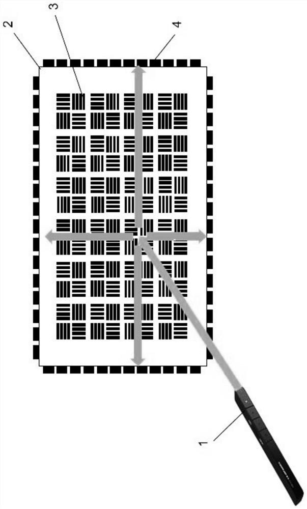
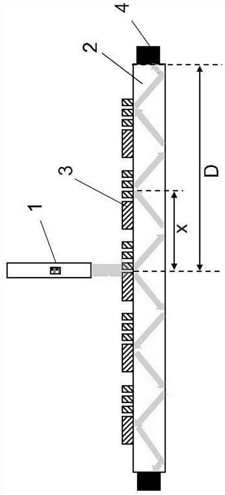
[0050] In order to overcome the deficiencies of the prior art, the present embodiment of the optical touch module A matrix structure based on two grating vector direction, reducing the thickness of the touch screen, to improve the coupling efficiency of the incident light and reduce light guiding waveguide layer transmission loss, and polarization characteristics using a grating, the grating structure by controlling such parameters with respect to the transverse electric field and a magnetic field transverse polarization diffraction efficiency of the grating are not equal, to increase the diffraction efficiency of the light coupled into the possible, and minimize the outcoupling efficiency of the light waveguide, and improve the overall efficiency of the optical output of the touch module.

[0051] Based on this embodiment, the...

Example Embodiment

[0069] Example 2

[0070] This embodiment realizes an optical touch module based on two vector direction point array raster structures.

[0071] In this embodiment, the optical touch module based on the two vector direction point array is specifically implemented on the basis of Example 1, and the laser source output 980 nm is not visible monochrome infrared light, and the grating vector direction is X and Y. Two directions, two vector direction dot matrix grating, etc., the duty cycle intersection, the entire waveguide guide layer, the grating period is 700 nm single period, the grating and the waveguide light-transumating layer material is a transparent PC, the refractive index is 1.62, The grating duty cycle is 0.5, the grating height is 500 nm, and the waveguide light guiding layer has a thickness of 1 mm. Figure 14 It is a schematic diagram of a lighttools simulation structure of an optical touch module, an optical touch module based on two vector direction point array raster...

Example Embodiment

[0075] Example 3

[0076] This embodiment realizes an optical touch module based on two vector direction point array raster structures.

[0077] In this embodiment, an optical touch module based on two vector direction point array raster structures is specifically implemented on the basis of Example 1. Figure 15 It is a schematic diagram of two vector directions of the multi-cycle grating combination based on two vector direction point array raster structures. Append Figure 15 As shown, the present embodiment is an optical touch module based on the two vector directed point array raster structure, the laser light source is output to a monochrome green light having 532 nm, the grating vector direction is X and Y two directions, two sets of direction gratings. The equalization of the cross-aligned distribution, covers the entire waveguide guide layer, two vector direction point array gratings, combined with 300 nm, 350 nm, 500 nm, and 700 nm period grating, each cycle grating in two...


PUM

PropertyMeasurementUnit
Thicknessaaaaaaaaaa
Heightaaaaaaaaaa
Refractive indexaaaaaaaaaa

Abstract

The invention relates to an optical touch module based on lattice grating structures in two vector directions. The optical touch module comprises a laser light source, a waveguide light guide layer, a grating and a photoelectric detector, the waveguide light guide layer is a single layer; the gratings are distributed on the waveguide light guide layer in the form of dot matrix units, and each dot matrix unit adopts two vector direction dot matrix grating structures and comprises a first vector direction dot matrix grating and a second vector direction dot matrix grating which are mutually straight with the waveguide light guide layer; the laser light source outputs incident light with a specific wavelength so as to meet the requirement that the diffraction angle of diffracted light in air is larger than 90 degrees, the diffracted light is incident on the waveguide light guide layer, the two vector direction lattice grating structures couple the diffracted light into the waveguide light guide layer, and two waveguide modes in different directions are generated. Incident light is transmitted to the side wall of the waveguide light guide layer along X and Y coordinate directions and is received by a peripheral photoelectric detector, so that the position of an incidence point of the laser light source is determined. The beneficial effects are that the output efficiency of the touch screen is improved and the screen thickness is reduced.

Description

【Technical field】 [0001] The invention relates to the technical field of touch display devices, in particular to an optical touch module based on two kinds of vector direction lattice grating structures.
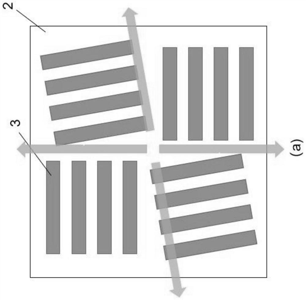
 【Background technique】 [0002] According to whether or not to touch the screen, touch technology can be divided into contact and non-contact touch technology. According to different touch sensing methods, contact touch technology can be subdivided into resistive, capacitive, acoustic and optical, and non-contact can be subdivided into camera and electromagnetic resonance. [0003] Resistive touch screens use pressure as an input and consist of two transparent sheets coated with a conductive substance, separated by a tiny space containing a particle fulcrum. When the finger touches the surface of the touch screen, due to the pressure, the two thin plates contact and conduct electricity, and the coordinates of the touch point are determined by detecting the voltage change of...

Claims


Application Information

Patent Timeline
IPC IPC(8): G06F3/042G02B6/34
CPCG06F3/042G06F3/0421G02B6/34
Inventor 王少康叶志成
Owner SHANGHAI JIAO TONG UNIV
Why Eureka
Try Eureka