
Pyrolyzing furnace pyrolysis material discharging device and discharging system

A discharge device, pyrolysis furnace technology, applied in the direction of discharge device, coke oven, coke cooling, etc., can solve the problems of peripheral fire, safety hazards of discharge machine, unable to meet actual needs, etc., to improve heat exchange effect , reduce the cooling water dead zone, increase the effect of turbulence

Active Publication Date: 2022-02-11
SHANDONG XIANGHUAN ENVIRONMENTAL TECH CO LTD +1
View PDF1 Cites 0 Cited by
  • Summary
  • Abstract
  • Description
  • Claims
  • Application Information

AI Technical Summary

Problems solved by technology

[0004] At present, all pyrolysis processes are to put the material to be pyrolyzed into the pyrolysis furnace for high-temperature pyrolysis, and the pyrolyzed material is discharged from the furnace through the discharge mechanism. The inventor found that the conventional discharge machine is used At this time, the pyrolysis furnace will produce a positive pressure tempering phenomenon, and the high-temperature pyrolysis gas that escapes through the discharge machine may cause peripheral fires. Therefore, the conventional discharge machine has potential safety hazards and cannot meet actual needs.

Method used


Image

  • Pyrolyzing furnace pyrolysis material discharging device and discharging system
  • Pyrolyzing furnace pyrolysis material discharging device and discharging system
  • Pyrolyzing furnace pyrolysis material discharging device and discharging system

Examples


Embodiment 1

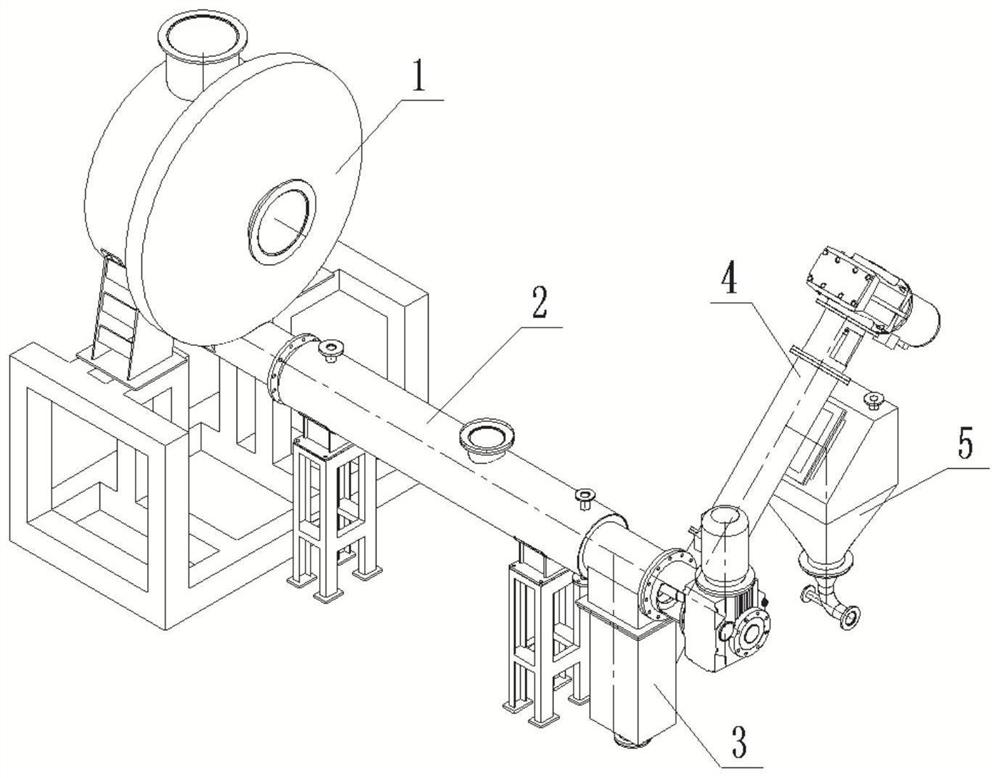
[0033] This embodiment provides a pyrolysis furnace pyrolysis material discharge device, such as Figure 1-Figure 3 As shown, it includes a first screw conveyor 2, a sealed box 3 and a second screw conveyor 4 connected in sequence.

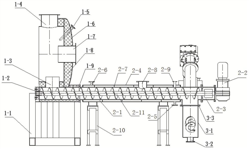
[0034] The first screw conveyor 2 adopts a shaft screw conveyor, including a first shell 2-1, the first shell is supported by a plurality of support frames 2-10, and one end of the first shell 2-1 can It is connected with the pyrolysis furnace discharge end cover shell of the pyrolysis furnace, and the other end of the first shell 2-1 is fixed with a driving element. In order to meet the needs of the working environment, the driving element adopts the first variable frequency explosion-proof motor 2-2 , the output shaft of the first variable frequency explosion-proof motor 2-2 is connected to the first material delivery mechanism through a coupling 2-3, and the first material delivery mechanism includes a main shaft and a helical blade fixed on th...

Embodiment 2

[0052] This embodiment provides a kind of pyrolysis furnace pyrolysis material discharge system, such as Figure 1-Figure 3 As shown, the pyrolysis furnace pyrolysis material discharging device described in embodiment 1 is included.

[0053] The first screw conveyor 2 is connected with the discharge end cover 1 of the pyrolysis furnace, the discharge end cover of the pyrolysis furnace can be connected with the pyrolysis furnace, and the pyrolysis charcoal powder of the pyrolysis furnace can enter the first screw conveyor.

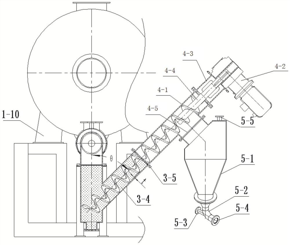
[0054] The discharge end cover of the pyrolysis furnace includes an end cover fixing frame 1-1, and one end of the end cover fixing frame 1-1 is welded and fixed with the end cover bracket 1-10, and the other end of the end cover bracket 1-10 is connected with the heat The discharge end cover housing 1-6 of the pyrolysis furnace is fixed, the discharge end cover housing 1-6 of the pyrolysis furnace is fixed on the end cover fixing frame 1-1, and the first s...


PUM

PropertyMeasurementUnit
distanceaaaaaaaaaa

Abstract

The invention relates to a pyrolyzing furnace pyrolysis material discharging device and a discharging system. The pyrolyzing furnace pyrolysis material discharging device comprises a horizontally-arranged first spiral conveyor, a material conveying mechanism of the first spiral conveyor comprises a first material conveying part and a second material conveying part, and the spiral directions of spiral blades of the first material conveying part and the second material conveying part are opposite; a discharging pipe of the first spiral conveyor corresponds to the junction position of the first material conveying part and the second material conveying part and is connected with a sealing box, the sealing box is connected with a shell of a second spiral conveyor, the second spiral conveyor is obliquely arranged relative to the horizontal plane, and the height of the discharging end is larger than that of the feeding end; and a conveying mechanism of the second spiral conveyor extends into the sealing box. By adopting the discharging device disclosed by the invention, carbon powder is continuously and stably output, and meanwhile, the sealing effect is good.

Description

technical field [0001] The invention relates to the technical field of drying and pyrolysis equipment, in particular to a discharge device and a discharge system for pyrolysis materials in a pyrolysis furnace. Background technique [0002] The statements herein merely provide background information related to the present invention and do not necessarily constitute prior art. [0003] Drying and pyrolysis of organic waste is the field of energy regeneration of organic matter. It is used to heat and crack organic solid waste such as domestic garbage, sludge, sludge, biomass (straw), coal chemical industry, petrochemical industry, and general industry to obtain the required substances. , such as combustible gas, tar, charcoal, etc. In recent years, it is a new concept and new way of harmless, resourceful and comprehensive utilization of organic waste, which is a harmonious resource and ecology. It can not only realize the cleaning and recycling of organic waste, but also has g...

Claims


Application Information

Patent Timeline
Patent Type & Authority Applications(China)
IPC IPC(8): C10B33/02C10B39/12
CPCC10B33/02C10B39/12
Inventor 朱振坤马春元张彪朱子霖闫瑞张鑫宋德升潘峰张立强王涛周滨选
Owner SHANDONG XIANGHUAN ENVIRONMENTAL TECH CO LTD
Features
  • Generate Ideas
  • Intellectual Property
  • Life Sciences
  • Materials
  • Tech Scout
  • Unparalleled Data Quality
  • Higher Quality Content
  • 60% Fewer Hallucinations
Learn More