
Thermoelectron and thermophotovoltaic coupling power generation system and working method thereof

A power generation system, thermal electron technology, applied in the field of thermal electron and thermo-photovoltaic coupling power generation system, can solve the problems of high anode temperature and low output voltage, and achieve the effect of improving power generation efficiency, increasing the number of net electrons, and increasing output voltage

Pending Publication Date: 2022-03-08
ZHEJIANG UNIV
View PDF0 Cites 0 Cited by
  • Summary
  • Abstract
  • Description
  • Claims
  • Application Information

AI Technical Summary

Problems solved by technology

[0007] In view of the above problems, the present invention provides a thermal electron and thermo-photovoltaic coupled power generation system and its working method. By using thermo-photovoltaic cells as thermo-electron anodes, thermo-photovoltaic power generation and thermo-electron power generation are coupled to improve thermo-electron and thermo-photovoltaic coupling. The output voltage and power generation efficiency of the power generation system solve the defects of low output voltage and high anode temperature of the existing thermal electron power generation system

Method used


Image

  • Thermoelectron and thermophotovoltaic coupling power generation system and working method thereof
  • Thermoelectron and thermophotovoltaic coupling power generation system and working method thereof
  • Thermoelectron and thermophotovoltaic coupling power generation system and working method thereof

Examples


no. 1 approach

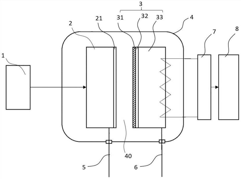
[0038] see figure 1 As shown, the present invention provides a thermal electron and thermal photovoltaic coupled power generation system, including an energy source 1, a thermal electron cathode 2, a thermal electron anode 3, a vacuum housing 4, a cathode wire 5 and an anode wire 6, and the energy source 1 is used for Thermionic cathode 2 is heated to cause thermionic cathode 2 to emit thermal electrons and photons; thermionic cathode 2 and thermionic anode 3 are separated in the vacuum housing 4 through a vacuum gap 40; thermionic anode 3 is a thermal photovoltaic cell , the thermionic anode 3 receives thermal electrons and photons; the cathode lead 5 is connected to the thermionic cathode 2, the anode lead 6 is connected to the thermionic anode 3, the cathode lead 5 and the anode lead 6 pass through the vacuum housing 4 and are connected to the external load ( (not shown in the figure) forms a closed loop.

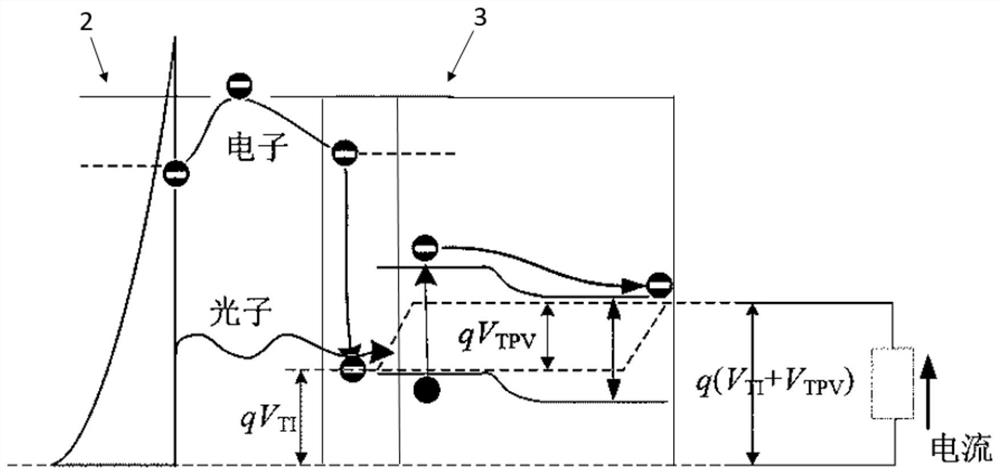
[0039] Such as figure 2As shown, the working principle of the pr...

no. 2 approach

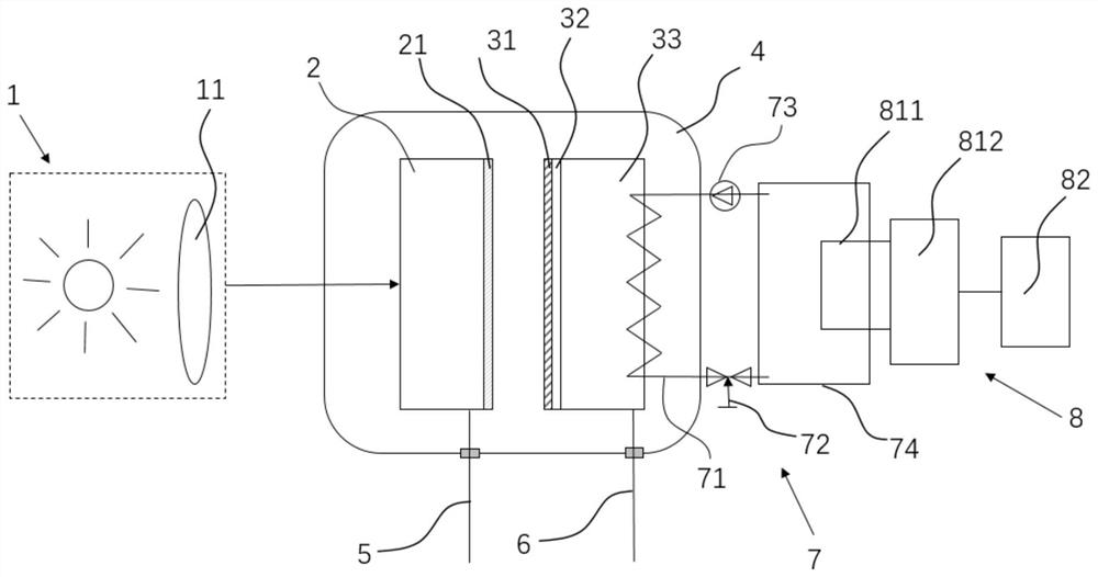
[0052] see image 3 As shown, the second embodiment of the present invention provides a thermal electron and thermo-photovoltaic coupled power generation system, which is basically the same structure as the power generation system of the first embodiment, the difference is that the energy source 1 is concentrated solar energy, and the concentrated Solar energy heats the thermionic cathode 2 through the concentrator 11, the first anode body layer 32 and the second anode body layer 33 are graphene film and n-type silicon respectively, and the thermionic cathode 2 is p-type silicon.

[0053] The working principle of the second embodiment of the present invention is basically the same as that of the first embodiment: the thermionic cathode 2 and thermionic anode 3 are separated by a vacuum gap 40, after the thermionic cathode 2 absorbs concentrated solar energy, the energy is higher than the band gap of the material The incident photons will excite electrons to transition from the...

no. 3 approach

[0059] see Figure 4 , Figure 5 As shown, the third embodiment of the present invention provides a thermal electron and thermo-photovoltaic coupled power generation system, which is basically the same in structure as the first embodiment and the second embodiment, the difference is that the energy source 1 is nuclear energy, The first anode body layer 32 and the second anode body layer 33 are graphene film and n-type silicon respectively. The thermo-electron and thermo-photovoltaic coupled power generation system is modularized into a columnar shape with a concentric annular cross-section. The heat of the nuclear fuel reaction is transferred to the thermo-electron cathode 2 and the thermo-electron cathode coating 21 through the fuel cladding 12. Its working principle is the same as that of the first embodiment , and the second embodiment are basically the same, and will not be repeated here. Although the third embodiment of the present invention shows that the thermal elect...


PUM


Abstract

The invention provides a thermo-electron and thermo-photovoltaic coupling power generation system and a working method thereof.The power generation system comprises an energy source, a thermo-electron cathode, a thermo-electron anode, a vacuum shell, a cathode wire and an anode wire, and the thermo-electron cathode and the thermo-electron anode are arranged in the vacuum shell in a spaced mode through a vacuum gap; the hot electron cathode is a hot electron battery, the hot electron anode is a hot photovoltaic battery, the cathode wire is connected with the hot electron cathode, the anode wire is connected with the hot electron anode, and the cathode wire and the anode wire penetrate out of the vacuum shell and form a closed loop with an external load. Photons emitted by the hot electron cathode are absorbed through the hot electron anode, the electron energy level of valence band electrons of the hot electron anode is excited to a conduction band from a semiconductor valence band, the output voltage is greatly improved, the power generation efficiency is improved, the difference of work functions of the hot electron cathode and the hot electron anode is overcome, and the output voltage is ensured; and the output voltage is difficult to further increase.

Description

technical field [0001] The invention relates to the technical field of thermoelectron and thermophotovoltaic power generation, in particular to a thermoelectron and thermophotovoltaic coupled power generation system and a working method thereof. Background technique [0002] Current typical solar power generation technologies mainly include Photovoltaic (PV) and Concentrating Solar Power (CSP, including dish type, tower type, trough type, etc.), both of which have inherent limitations. Single photovoltaic power generation is easily affected by sunlight fluctuations, and the power output is not stable enough. Usually, only part of the band of photons can be used, and the theoretical efficiency is limited. Photothermal power generation converts sunlight into heat energy, but does not make efficient use of the quantum properties of high-frequency photons, and the structure of the photothermal power generation system is relatively complex, requiring high construction and operati...

Claims


Application Information

Patent Timeline
Patent Type & Authority Applications(China)
IPC IPC(8): H02S10/30
CPCH02S10/30Y02E10/50
Inventor 肖刚邱浩倪明江岑可法
Owner ZHEJIANG UNIV
Learn More