Ripple reduction circuit based on input feedforward and loop control and coating power supply

A loop control and control circuit technology, applied in the power supply field, can solve the problems of high cost, untimely dynamic response of fast input or output, and poor real-time performance of digital control.

Pending Publication Date: 2022-03-11
固赢科技(深圳)有限公司
View PDF4 Cites 0 Cited by
  • Summary
  • Abstract
  • Description
  • Claims
  • Application Information

AI Technical Summary

Problems solved by technology

[0005] Need to add a digital chip, and 3.3V power supply line, etc., the cost is very high
Moreover, the real-time performance of digital control is very poor, and it can suppr...

Method used


Image

  • Ripple reduction circuit based on input feedforward and loop control and coating power supply
  • Ripple reduction circuit based on input feedforward and loop control and coating power supply

Examples


Embodiment 1

[0064] The control strategy of conventional semiconductor coating power supply and photovoltaic coating power supply is generally AC rectification to DC+isolated voltage-regulated pulse output, or use PFC circuit + isolated voltage-regulated pulse output, resulting in the output of external alternating current with 100Hz or 300Hz after being rectified by the rectifier The DC voltage with low-frequency ripples reduces the efficiency of the power supply, and it is easy to generate harmonics on the back-end electrical equipment, resulting in damage to the back-end electrical equipment. The existing technology cannot achieve ultra-high-performance dynamic response in the process of suppressing low-frequency ripple, and cannot solve the problem of chip damage caused by excessive signal amplitude extracted by the differential extraction circuit in the filtering and phase-shifting process.

[0065] In view of the above problems, the embodiment of the present application provides a rip...

Embodiment 2

[0077] For ease of understanding, an embodiment of a ripple reduction circuit based on input feedforward and loop control is provided below for illustration. In practical applications, a circuit that couples the voltage loop control circuit and the filtering phase-shifting limiting circuit for further design.

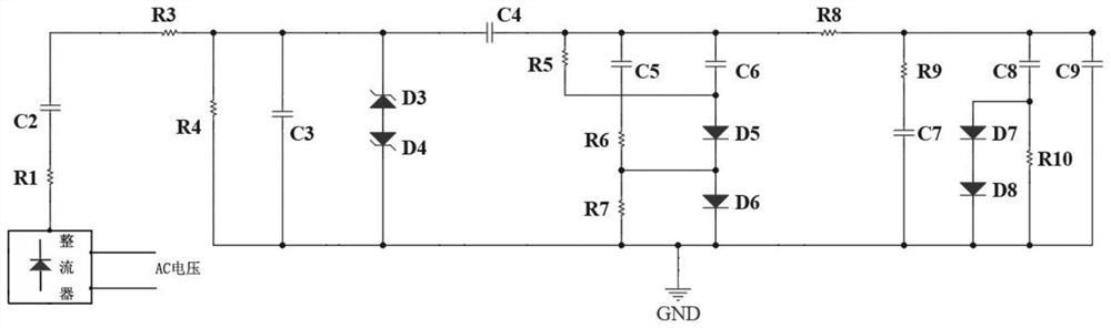
[0078] see figure 2, Embodiment 2 of the ripple reduction circuit based on input feedforward and loop control shown in the embodiment of the present application includes:

[0079] The differential extraction circuit includes a resistor R1 and a capacitor C2, the resistor R1 and the capacitor C2 are connected in series, and the resistor R1 is connected to the positive output terminal of the rectifier.

[0080] The filtering phase-shifting circuit includes a resistor R3, a resistor R4 and a capacitor C3, the resistor R3 and the capacitor C2 are connected in series, the resistor R4 and the resistor R3 are connected in series, the resistor R4 and the capacitor C3 are conn...

Embodiment 3

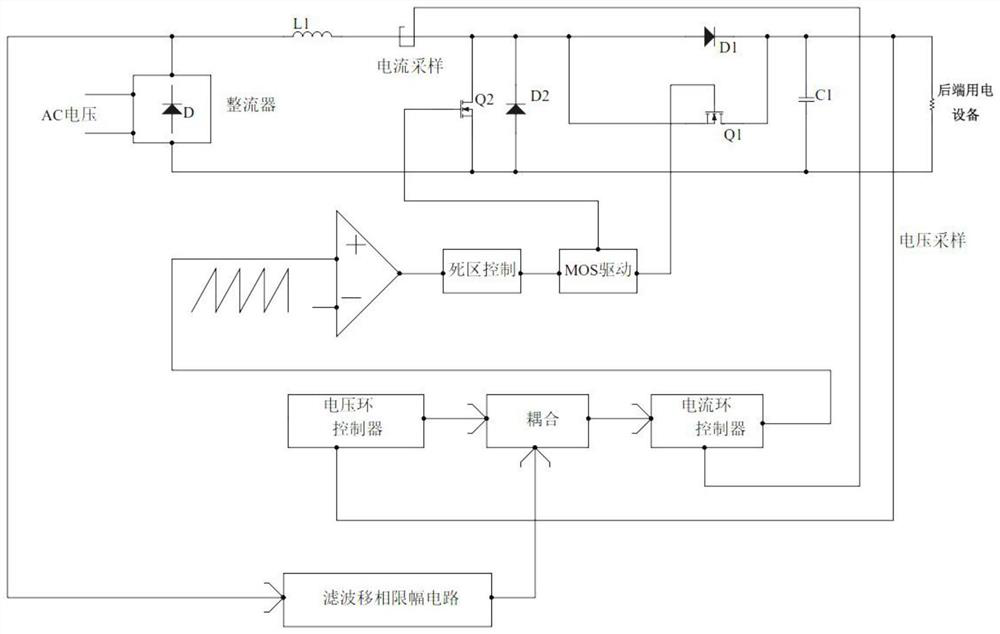
[0087] For ease of understanding, an embodiment of a ripple reduction circuit based on input feedforward and loop control is provided below for illustration. In practical applications, the working mode of the boost circuit will be determined by a pulse width modulation signal generator, and also Prevent the MOS transistor Q1 and MOS transistor Q2 in the boost circuit from being turned on at the same time, causing damage to the back-end electrical equipment.

[0088] see figure 1 , Embodiment 3 of the ripple reduction circuit based on input feedforward and loop control shown in the embodiment of the present application includes:

[0089] Dynamic voltage signal input pulse width modulation signal generator, pulse width modulation signal generator includes: comparator T1, MOS transistor drive circuit and pulse width modulation signal generation circuit;

[0090] The pulse width modulation signal generating circuit is used to output a triangle wave;

[0091] The comparator T1 is...


PUM


Abstract

The invention relates to a ripple reduction circuit based on input feedforward and loop control. The circuit comprises a rectifier, a voltage loop control circuit, a filtering phase-shifting amplitude limiting circuit and a booster circuit, the output end of the rectifier is connected with the input end of the filtering phase-shifting amplitude limiting circuit; a first coupling voltage output by the voltage loop control circuit is coupled with a second coupling voltage output by the filtering phase-shifting amplitude limiting circuit to obtain a coupling voltage signal; processing the coupling voltage signal through a current loop controller to obtain a dynamic voltage signal; the filtering phase-shifting amplitude limiting circuit comprises a differential extraction circuit, a filtering phase-shifting circuit, an amplitude limiting circuit and a filtering phase-shifting coupling circuit; the voltage loop control circuit comprises a voltage loop controller and a voltage loop coupling circuit; and the output end of the current loop controller is connected with the pulse width modulation signal generator. According to the scheme, low-frequency ripples can be restrained, the system can achieve ultra-high-speed response, the high-performance requirement is met, and the situation that rear-end electric equipment is damaged is avoided.

Description

technical field [0001] The present application relates to the field of power supply technology, in particular to a ripple reduction circuit and a coating power supply based on input feedforward and loop control. Background technique [0002] The control strategy of conventional semiconductor coating power supply and photovoltaic coating power supply is generally AC rectification to DC+isolated voltage-regulated pulse output, or use PFC circuit + isolated voltage-regulated pulse output, resulting in the output of external alternating current with 100Hz or 300Hz after being rectified by the rectifier The DC voltage with low-frequency ripples reduces the efficiency of the power supply, and it is easy to generate harmonics on the back-end electrical equipment, resulting in damage to the back-end electrical equipment. [0003] In the prior art, in the patent with publication number CN108512451B (Digital control device for low-frequency ripple suppression of flyback micro-inverter...

Claims


Application Information

Patent Timeline
IPC IPC(8): H02M1/14H02M3/158
CPCH02M1/14H02M3/158H02M3/1588Y02B70/10
Inventor 刘力张小彬
Owner 固赢科技(深圳)有限公司
Why Eureka
Try Eureka