
Oil film removal system and method

An oil film and oil separation technology, applied in chemical instruments and methods, grease/oily substance/float removal devices, special treatment targets, etc. and other problems, to achieve the effect of short commissioning cycle, reducing oil adhesion, and low heating temperature difference

Pending Publication Date: 2022-03-29
新疆德安环保科技股份有限公司
View PDF0 Cites 0 Cited by
  • Summary
  • Abstract
  • Description
  • Claims
  • Application Information

AI Technical Summary

Problems solved by technology

Oily wastewater requires multiple processes for treatment and reinjection. Currently, according to the "Injection Water Quality Index and Analysis Method for Clastic Reservoirs" SY / T5329-2012, the oil content is less than 5pp, the suspended solid content is less than 1ppm, and the median diameter of suspended solid particles is less than 1um. Referred to as "511" standard (the highest standard for reinjection water); this requires strict treatment of reinjected oily wastewater. The quality of the membrane will cause the membrane to be replaced after two years of use. During this period, a large amount of chemicals are needed for cleaning, and the operating cost is too high. Secondly, the current membrane treatment equipment mainly uses organic membranes. Although organic membranes are relatively economical, they have low strength and poor anti-pollution performance. Poor, long pretreatment process, easy fouling of the membrane and rapid decay of membrane flux, reduced degreasing effect, high cost of degreasing, etc.

Method used


Image

  • Oil film removal system and method

Examples


Embodiment Construction

[0036] The following will clearly and completely describe the technical solutions in the embodiments of the present invention with reference to the accompanying drawings in the embodiments of the present invention. Obviously, the described embodiments are only some, not all, embodiments of the present invention. Based on the embodiments of the present invention, all other embodiments obtained by persons of ordinary skill in the art without making creative efforts belong to the protection scope of the present invention.

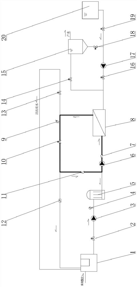
[0037] see figure 1 , in the embodiment of the present invention, the degreasing film system and method comprise oil separation adjustment tank 1, bag filter 5, polyceramic membrane 8, produced water tank 15 and medicine washing backwash tank 20, and oil separation adjustment tank 1 passes through the first The pipeline is connected with the first electromagnetic valve 2, the first electromagnetic valve 2 is connected with the water inlet pump 3 through the se...


PUM


Abstract

The invention discloses an oil removal membrane system and method. The oil removal membrane system comprises an oil removal adjusting tank, a bag filter, a poly ceramic membrane, a water production tank and a chemical backwashing tank. According to the oil removal membrane system and method, water is produced through the flow of oily wastewater, the oil removal regulating reservoir, the poly ceramic membrane, the water production tank and water production, so that a plurality of process units are reduced, the operation cost and the equipment failure rate are reduced, the process flow is short, the debugging period is short, and the debugging time is saved. The polymer ceramic membrane is adopted and has the characteristic of high temperature resistance, the temperature of produced water is 55 DEG C, cooling treatment is not needed, the heating temperature difference of treated reinjection water is low, energy is saved, and the energy consumption of the system is reduced. A high-flow-rate filtering design is adopted, the flow rate of oily wastewater is increased, multiple times of circulating filtration are achieved, oil stains attached to the surface of an oil removal film are effectively reduced, the water production rate is kept stable, the backwashing frequency, especially the chemical backwashing frequency, is reduced, and the fluid flow loss caused by the influence of a water inlet pump on circulating circulation is effectively reduced by arranging a one-way valve on a bypass.

Description

technical field [0001] The invention relates to the technical field of oil-water separation, in particular to an oil removal film system and method. Background technique [0002] Petroleum wastewater generally refers to petroleum industry wastewater. It mainly includes three aspects: petroleum extraction wastewater, oil refining wastewater and petrochemical wastewater. Oily waste water is discharged during the dehydration process of the crude oil extracted from the oil field. At present, the traditional process of air flotation is mostly used, and with the oil recovery. As the oilfield continues to be exploited, the water content in the produced fluid reaches 70-80%, and some oilfields even reach 90%. In the Karamay oil production area of ​​Xinjiang, some oil wells currently produce oil with a water content of 70-80%, and the outlet temperature is relatively high (50-60°C). Oily wastewater requires multiple processes for treatment and reinjection. Currently, according to ...

Claims


Application Information

Patent Timeline
Patent Type & Authority Applications(China)
IPC IPC(8): C02F9/02C02F103/10C02F103/34C02F103/36
CPCC02F9/00C02F1/001C02F1/40C02F1/44C02F2303/16C02F2303/14C02F2103/10C02F2103/365C02F2103/34
Inventor 田文杰马莉达张琳琳刘海燕高可可李洁
Owner 新疆德安环保科技股份有限公司
Learn More