Low-nitrogen emission submerged combustion type gasifier

A submerged combustion and nitrogen emission technology, applied in the direction of burners, gas fuel burners, combustion types, etc., can solve problems such as easy to block the filter screen, reduce the concentration of nitrogen oxides, stabilize production and smoke control difficulties, etc., to achieve convenient Disassembly and maintenance, good heat preservation effect

Pending Publication Date: 2022-05-03
CHINA PETROLEUM & CHEM CORP +1
View PDF0 Cites 0 Cited by
  • Summary
  • Abstract
  • Description
  • Claims
  • Application Information

AI Technical Summary

Problems solved by technology

Generally speaking, the pore size of the water injection nozzle is very small, and the filter screen of the water injection pipeline is 40-200 mesh, and the impurities in the water bath, especially the sediment in the cement water bath, can easily block the filter screen and nozzle, which will affect the stability of production and flue gas. The control has brought many difficulties, and the simple water injection cooling is not enough to reduce the concentration of nitrogen oxides in the flue gas to the current environmental protection standard

Method used


Image

  • Low-nitrogen emission submerged combustion type gasifier
  • Low-nitrogen emission submerged combustion type gasifier
  • Low-nitrogen emission submerged combustion type gasifier

Examples


Embodiment Construction

[0029] The present invention provides a low-nitrogen emission submerged combustion gasifier. In order to make the purpose, technical solution and effect of the present invention clearer and clearer, the present invention will be further described in detail below. It should be understood that the specific embodiments described here are only used to explain the present invention, not to limit the present invention.

[0030] In the description of the present invention, it should be understood that the orientation or positional relationship indicated by the terms "top", "bottom", "upper", "lower", "inner" and "outer" are based on the orientation shown in the accompanying drawings. Orientation or positional relationship is only for the convenience of describing the present invention and simplifying the description, and does not indicate or imply that the referred device or element must have a specific orientation, be constructed and operated in a specific orientation, and thus shoul...


PUM


Abstract

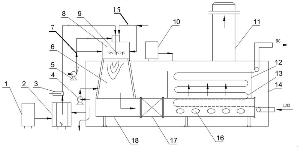
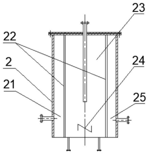
The invention discloses a low-nitrogen emission submerged combustion gasifier which comprises a combustor, a combustion chamber, a flue gas distributor, a weir flow box, a heat exchange tube bundle and a water tank, the combustion chamber, the flue gas distributor, the weir flow box and the heat exchange tube bundle are all arranged in the water tank, and a waste gas chimney is arranged at the top of the water tank; an inlet of the combustor is connected with an air pipeline, a combustible gas pipeline and a denitrifying agent pipeline, a denitrifying agent nozzle which sprays downwards is arranged in the combustor, one end of the denitrifying agent pipeline is communicated with the denitrifying agent nozzle, and the other end of the denitrifying agent pipeline is connected with a denitrifying agent storage tank and a stirring type water purification tank; a flue and a denitrification reactor which are communicated in sequence are arranged between the combustion chamber and the flue gas distributor, and two ends of the denitrification reactor are respectively connected with the flue and the flue gas distributor through flanges. According to the submerged combustion type gasifier, the nitrogen reduction effect is achieved at the front combustion end and the rear combustion end at the same time, the emission concentration of nitrogen oxide is lower than 30 mg / m < 3 >, and the environment-friendly emission requirement is met.

Description

technical field [0001] The invention relates to the technical field of gasifiers for liquefied natural gas, in particular to a low-nitrogen emission submerged combustion gasifier. Background technique [0002] As an efficient and clean energy source, natural gas (NG for short) has seen a substantial increase in domestic applications in recent years. When importing natural gas, in order to facilitate storage and transportation, the natural gas is liquefied into low-temperature liquefied natural gas (LNG for short). After arriving at the port, the LNG is stored in the storage tank of the coastal receiving station. When it is supplied to users, it needs to be gasified into NG. delivery. At present, there are mainly three types of gasifiers for LNG receiving stations in China, namely open rack gasifier (ORV for short), intermediate medium vaporizer (IFV for short) and submerged combustion gasifier (SCV for short). According to the environment and operating conditions, select t...

Claims


Application Information

Patent Timeline
Patent Type & Authority Applications(China)
IPC IPC(8): F23D14/48F23D14/78F23J7/00F28D1/047B01D53/86B01D53/56B01D35/027F17C7/04
CPCF23D14/48F23D14/78F23J7/00F28D1/0477F17C7/04B01D53/8631B01D35/027F23J2219/10F23J2215/10
Inventor 吴斌刘博李春奇郑元杰韩荣鑫孟昭宇
Owner CHINA PETROLEUM & CHEM CORP
Why Eureka
Try Eureka