High-efficiency plate-type ozone generator discharge chamber

A technology of ozone generator and discharge chamber, which is applied in the field of gas preparation, can solve problems such as restricting the engineering application of ozone generators, difficulty in meeting the needs of practical applications, and reducing the effective output concentration of ozone, so as to reduce assembly differences, increase reliability, Effect of Power Consumption Reduction

Pending Publication Date: 2022-07-05
北京安力斯环境科技股份有限公司
View PDF12 Cites 0 Cited by
  • Summary
  • Abstract
  • Description
  • Claims
  • Application Information

AI Technical Summary

Problems solved by technology

[0003] Studies have shown that the higher the ozone concentration, the more obvious the pollution treatment effect, especially in the fields of silicon wafer cleaning, photoresist removal, atomic layer deposition ALD, molecular beam epitaxy ALE and other processes in semiconductor processing, and medical high-concentration ozone water. The concentration of ozone needs to exceed 20%wt. The current output concentration of ozone generators is usually 7%wt~15%wt, which is difficult to meet the needs of practical applications. Although it is reported that foreign universities have successfully developed ozone with an output concentration of 20.85%wt. Generator, but expensive, complex structure, harsh operating conditions, difficult engineering application;
[0004] The principle of the ozone generator is to use high-voltage discharge technology to ionize oxygen to generate electrochemical reactions, thereby generating ozone. However, ozone is extremely unstable, and its half-life in a standard environment is about 30 minutes. At 100°C, ozone decomposes very violently. When it reaches a high temperature of 270°C, it can be decomposed and converted into oxygen immediately. At present, the most efficient ozone gen...

Method used


Image

  • High-efficiency plate-type ozone generator discharge chamber
  • High-efficiency plate-type ozone generator discharge chamber
  • High-efficiency plate-type ozone generator discharge chamber

Examples


Embodiment Construction

[0035] The technical solutions in the embodiments of the present invention will be clearly and completely described below with reference to the accompanying drawings in the embodiments of the present invention. Obviously, the described embodiments are only a part of the embodiments of the present invention, but not all of the embodiments. Based on the embodiments in the present invention, all other embodiments obtained by those of ordinary skill in the art fall within the protection scope of the present invention.

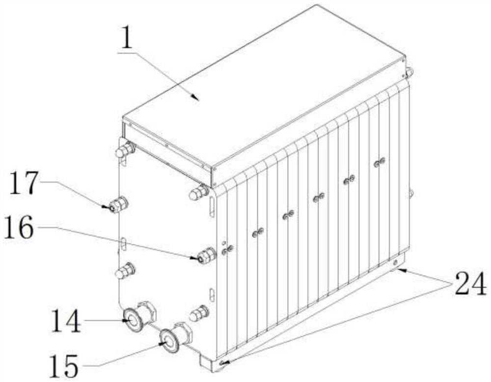
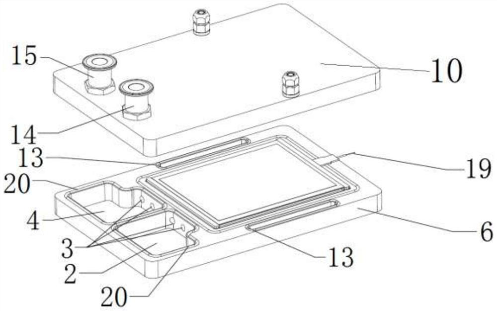
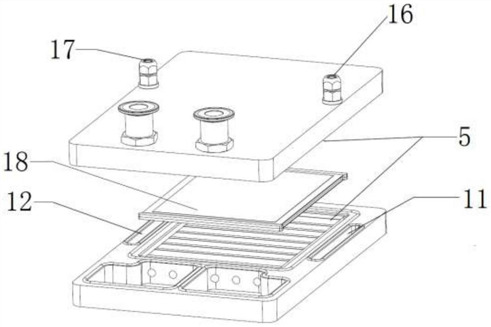
[0036] As shown in Figures 1-8, a high-efficiency plate-type ozone generator discharge chamber according to an embodiment of the present invention includes a plurality of ground plate units 6, and each of the ground plate units 6 is provided with a first The buffer chamber 2 and the second buffer chamber 4, the ground plate units 6 on both sides are respectively connected with the blocking plate 10 through locking bolts, the first buffer chamber 2 and the second buf...


PUM


Abstract

The invention discloses an efficient plate-type ozone generator discharge chamber, which comprises a plugging plate, an inlet and outlet flange, a buffer chamber, a water path sealing ring, a gas path sealing ring, a gas guide groove and a plurality of ground pole plate units, a first buffer chamber and a second buffer chamber are arranged in each of the plurality of ground pole plate units, and the top of each ground pole plate unit is connected with a front plugging plate. The first buffer chamber and the second buffer chamber are connected through a U-shaped parallel circuit, a multi-channel groove air gap is formed in one side of the first buffer chamber and one side of the second buffer chamber, and a ground pole plate, a ceramic plate and a rubber plate are sequentially arranged at the top of the multi-channel groove air gap. Through the special design of the earth pole plate, the ceramic plate, the rubber plate and the sealing ring, the complete gas path and cooling path design is formed in the discharge chamber, so that the discharge chamber is more compact in structure and simple in interface, each unit is fastened by transverse pressure, the integrity of the gas path and the cooling path is ensured through the linear sealing of the sealing ring, and the hidden danger of leakage is avoided.

Description

technical field [0001] The invention relates to the technical field of gas preparation, in particular to a discharge chamber of a high-efficiency plate-type ozone generator. Background technique [0002] The development of modern industry has led to a sharp increase in the number and types of organic matter entering water, atmosphere and soil, and the pollution is increasing day by day, especially the high-concentration and refractory organic matter, which has the characteristics of complex composition, poor biodegradability, serious pollution and high toxicity. Conventional treatment processes have been difficult to meet the purification requirements. Advanced oxidation technology using high-concentration ozone is the most ideal solution at present. It has a high killing rate and fast speed of other microorganisms, and completely removes pollutants such as organic compounds without causing secondary pollution. It is an "ideal universal green strong oxidizing agent". The use...

Claims


Application Information

Patent Timeline
IPC IPC(8): C01B13/11
CPCC01B13/11
Inventor 蔡晓涌李红涛张瑞波杨影丽
Owner 北京安力斯环境科技股份有限公司
Why Eureka
Try Eureka