Exhaust utilization device of solid fuel cell

A solid fuel cell and fuel technology, applied in solid electrolyte fuel cells, fuel cells, electrical components, etc., can solve problems such as adverse environmental effects, avoid sensible heat loss, reduce the thickness of the liquid film layer, and reduce the concentration of CO2 at the outlet. reduced effect

Pending Publication Date: 2022-07-08
江苏群菱能源科技有限公司 +1
View PDF0 Cites 0 Cited by
  • Summary
  • Abstract
  • Description
  • Claims
  • Application Information

AI Technical Summary

Problems solved by technology

If the anode exhaust gas is fully mixed with pure oxygen, the product after complete combustion is only CO 2 and H 2 O, and CO 2 The concentration is higher, if the high concentration of CO 2 Direct discharge into the air can cause adverse effects on the environment

Method used


Image

  • Exhaust utilization device of solid fuel cell
  • Exhaust utilization device of solid fuel cell
  • Exhaust utilization device of solid fuel cell

Examples


Embodiment 1

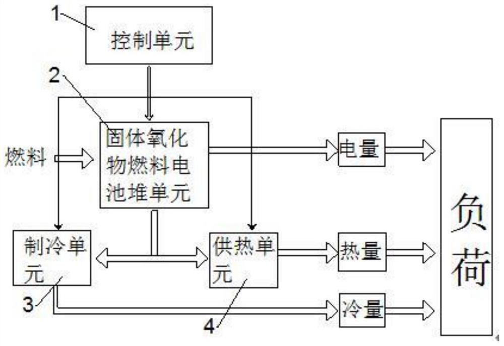
[0034] combine figure 2 , an exhaust gas utilization device of a solid fuel cell, including a battery stack unit 2 for providing electrical energy, including a control unit 1 for controlling the battery stack unit 2, and the exhaust gas of the battery stack unit 2 is the refrigeration unit 3 and the power supply unit. The heating unit 4 provides energy, the control unit 1 controls the switching of the working mode between the heating unit 4 and the cooling unit 3, the battery stack unit 2 is mainly used for power generation, and the control unit 1 predicts the demand and feedback according to the power of the load. The real-time data is compared to adjust the power output of the battery stack unit 2 to meet the needs of the load. The battery stack unit 2 will generate a lot of energy while generating electricity, and this energy will be used for the cooling unit 3 and the heating unit 4 to provide users with The heat and cooling required for daily life have achieved the effec...

Embodiment 2

[0037] Since the outlet of the anode of the stack unit will be discharged by H 2 , CO, H 2 O, CO 2 and CH 4 In order to carry out low-carbon emission treatment of the exhaust gas, the exhaust gas discharged from the anode is transported to the capture unit to achieve the purpose of emission reduction and environmental protection.

[0038] combine Figure 4 , the capture unit comprises that the tail gas of the anode and cathode of the battery stack unit 2 enters the waste heat boiler steam turbine one 5 after catalytic combustion, the waste heat boiler steam turbine one 5 is used for power generation, and the waste heat boiler steam The exhaust gas of turbine one 5 enters CO 2 High temperature separation membrane 7, the CO 2 Separated from the exhaust gas, the anode of the battery stack unit 2 adopts pure O 2 As the oxidant of the anode fuel, the anode of the cell stack unit 2 undergoes an electrochemical reaction of CO to generate high-temperature CO. 2 The exhaust gas ...

Embodiment 3

[0042] the CO 2 The high temperature separation membrane 7 adopts a hollow fiber membrane contactor, and the CO 2 High temperature separation membrane 7 uses amino acid salt as CO 2 Collecting agent, inorganic salt potassium borate and piperazine are added to the amino acid salt solution as activators to form a composite absorbent, and the composite absorbent will affect the absorption of CO by the amino acid salt 2 process that accelerates CO 2 mass transfer efficiency.

[0043] the CO 2 The mass transfer coefficient K of the high temperature separation membrane satisfies: K=Gln(C in / C out ) / AL, where G is the gas flow rate (m 3 / s), A is the cross-sectional area of ​​the membrane structure (m 2 ), L is the effective length of the membrane structure (m), C in and C out are the CO in the gas phase inlet and outlet of the separation membrane structure, respectively 2 concentration (mol / L).

[0044] the CO 2 The mass transfer flux W of the high temperature separatio...


PUM


Abstract

The invention relates to an exhaust gas utilization device of a solid fuel cell, which comprises a cell stack unit for providing electric energy and a control unit for controlling the cell stack unit, and exhaust gas of the cell stack unit provides energy for a refrigeration unit and a heat supply unit. The control unit is used for controlling the switching of working modes between the heating unit and the refrigerating unit; the cell stack unit is further connected with a capturing unit, the capturing unit comprises that tail gas of an anode and a cathode of the cell stack unit enters a waste heat boiler steam turbine I after being subjected to catalytic combustion, the waste heat boiler steam turbine I is used for electric power generation, and tail gas of the waste heat boiler steam turbine I enters a CO2 high-temperature separation membrane; cO2 is separated from the tail gas; according to the exhaust utilization device provided by the invention, one part of high-temperature and high-concentration CO2 tail gas generated during power generation of the fuel cell is circulated to serve as fuel of the fuel cell, and the rest CO2 tail gas is utilized and captured, so that low-carbon emission is realized.

Description

technical field [0001] The invention belongs to the technical field of fuel cells, and in particular relates to an exhaust gas utilization device of a solid fuel cell. Background technique [0002] with H 2 , CH 4 , biomass energy and various organic wastes as fuel fuel cells, is an ideal energy conversion device for future development. Fuel cells convert chemical energy directly into electrical energy and are not bound by the Carnot cycle, so their efficiency is usually much higher than that of internal combustion engines. At the same time, it is very quiet during operation, and there is almost no emission of NOx, SOx and particulate dust. It is the best choice for green energy. The relationship between ordinary battery power and capacity is closely related and cannot be very large, while fuel cells allow arbitrary scaling between power (fuel cell size) and capacity (fuel storage size), which can be very It is easy to go from the kW level to the MW level, which can rela...

Claims


Application Information

Patent Timeline
Patent Type & Authority Applications(China)
IPC IPC(8): H01M8/0668H01M8/12B01D53/14B01D53/18B01D53/22
CPCH01M8/0668B01D53/18B01D53/1475B01D53/228H01M2008/1293B01D2053/221Y02E60/50
Inventor 姚承勇张进滨姚海强
Owner 江苏群菱能源科技有限公司
Why Eureka
Try Eureka