
Membrane for an electrochemical device, electrochemical device comprising the membrane, and method of manufacturing an

A battery and secondary battery technology, applied in electrolyte battery manufacturing, electrode manufacturing, battery electrodes, etc., can solve problems such as reducing ionic conductivity, and achieve the effects of improving dry adhesion and ionic conductivity.

Pending Publication Date: 2022-08-05
LG ENERGY SOLUTION LTD
View PDF5 Cites 0 Cited by
  • Summary
  • Abstract
  • Description
  • Claims
  • Application Information

AI Technical Summary

Problems solved by technology

[0006] However, the porous coating is a densely packed structure of inorganic particles, and thus, the separator has a greatly reduced ionic conductivity compared to the porous polymer substrate used as the separator

Method used


Image

  • Membrane for an electrochemical device, electrochemical device comprising the membrane, and method of manufacturing an
  • Membrane for an electrochemical device, electrochemical device comprising the membrane, and method of manufacturing an
  • Membrane for an electrochemical device, electrochemical device comprising the membrane, and method of manufacturing an

Examples


Embodiment 1

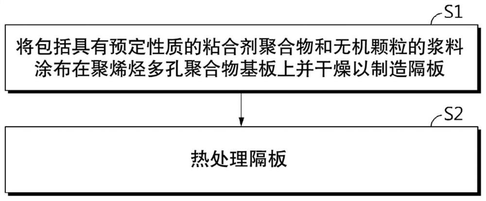
[0186] [Manufacture of separator]

[0187] Aluminum hydroxide (Al(OH) as inorganic particles 3 ) and polyvinylidene fluoride hexafluoropropylene (PVDF-HFP, weight average molecular weight: 700,000, HFP content: 10%) as a binder polymer were added to an acetone solvent in a weight ratio of 80:20 to prepare porous coating slurry.

[0188] The prepared slurry for forming a porous coating layer was coated on both surfaces of a 9 μm thick polyethylene porous polymer substrate (porosity: 43%, air permeation time: 110 sec, resistance 0.45 ohm) by dip coating and at 23 Drying was carried out under the conditions of ℃ and 40% relative humidity to produce the initial separator with the porous coating.

[0189] Subsequently, the initial separator was wetted in dimethyl carbonate as an organic solvent, and heat-treated at 80° C. for 3 hours to manufacture the final separator.

Embodiment 2

[0191] The separator was manufactured by the same method as in Example 1, except that polyvinylidene fluoride hexafluoropropylene (PVDF-HFP, weight average molecular weight: 700,000, HFP content: 15%) was used as a binder polymer instead of polyvinylidene fluoride hexafluoropropylene (PVDF-HFP, weight average molecular weight: 700,000, HFP content: 10%).

experiment example 1

[0218] The ionic conductivities of the separators manufactured in Examples 1 to 2 and Comparative Examples 1 to 6 were measured and compared.

[0219] The ionic conductivity of the separator was measured as follows: coin half-cells were fabricated using the separator alone and impregnated with an organic solvent including ethylene carbonate (EC) and dimethyl carbonate (DMC) in a volume ratio of 3:7 and 1.0 M LiPF 6 of non-aqueous electrolytes.

[0220] [Table 1]

[0221]

[0222] from Table 1 and Figure 4 It can be seen that Comparative Examples 1 to 2, which were not subjected to the heat treatment process, had lower separator ionic conductivity than Examples 1 to 2, which were subjected to the heat treatment process. Figure 4 The level of ionic conductivity improvement as a function of comonomer content is shown. Furthermore, from Figure 4 As can be seen from Comparative Examples 4 and 6 in Table 1, even after the heat treatment process was performed, when the con...


PUM

PropertyMeasurementUnit
electrical conductivityaaaaaaaaaa
crystallinityaaaaaaaaaa
electrical conductivityaaaaaaaaaa

Abstract

One aspect of the present disclosure relates to a separator for a lithium secondary battery, comprising a porous polymer substrate and a porous coating layer formed on at least one surface of the porous polymer substrate, in which the separator has an ionic conductivity of 4.75 * 10 <-5 > S / cm or more, and the porous coating includes an interstitial volume and macropores having a diameter greater than the interstitial volume together, and a method of making the same. Thus, a separator having significantly improved ionic conductivity compared to commercial separators is provided.

Description

technical field [0001] This application claims priority from Korean Patent Application No. 10-2019-0171169 filed in Korea on December 19, 2019 and Korean Patent Application No. 10-2019-0172441 filed in Korea on December 20, 2019, The disclosures of the aforementioned patent applications are incorporated herein by reference. The present disclosure relates to a separator for an electrochemical device, an electrochemical device including the separator, and a method of manufacturing the electrochemical device. Background technique [0002] Recently, energy storage technology has received increasing attention. As the application of energy storage technology has expanded to use in mobile phones, video cameras and notebook computers, and even electric vehicles, many efforts have been made to develop electrochemical devices. In this regard, electrochemical devices are receiving more attention, especially, the development of rechargeable secondary batteries is a focus, and recently...

Claims


Application Information

Patent Timeline
Patent Type & Authority Applications(China)
IPC IPC(8): H01M50/403H01M50/446H01M50/449H01M10/058H01M10/052H01M4/04H01M50/46
CPCH01M50/403Y02E60/10Y02P70/50H01M50/426H01M50/443H01M50/497H01M50/417H01M10/446H01M4/0447H01M10/0569H01M10/058H01M10/0525H01M50/446H01M50/449H01M10/052H01M50/46H01M50/491H01M50/609H01M10/049
Inventor 金大洙金荣德催贤俊金锡九池秀元
Owner LG ENERGY SOLUTION LTD
Learn More