
Sludge burning treatment method and system

A sludge incineration and treatment method technology, applied in the direction of combustion method, oxidation treatment sludge, incinerator, etc., can solve the problems of huge investment in treatment equipment, large sludge output, high operating costs, etc., and achieve combustion stability Good, reduced NOx and CO formation, rapid combustion effect

Inactive Publication Date: 2006-08-23
常州广源热电有限公司 +1
View PDF0 Cites 12 Cited by
  • Summary
  • Abstract
  • Description
  • Claims
  • Application Information

AI Technical Summary

Problems solved by technology

However, there are many problems in the sanitary landfill of municipal sludge: various toxic substances in the landfill are eroded and leaked by rainwater, so that some pollutants in the sludge enter the deep layer of the ground and pollute the groundwater environment, so sanitary landfill The sludge treatment method is extremely unsafe for areas where groundwater is the domestic water source; in addition, the sites suitable for landfilling sludge are also becoming less and less due to the large output of urban sludge, and the various costs of the site also getting higher
The advantage of the dry incineration method is that there are few residues produced by incineration, and the ash after incineration has no peculiar smell; however, the investment in the treatment equipment for dry incineration is huge, the operating cost is high, and a large amount of waste gas is generated, so the dry incineration of sludge is mainly used In the following cases: the quality of the sludge is too poor or the sludge output is too large or the existing landfill site is insufficient

Method used


Image

  • Sludge burning treatment method and system
  • Sludge burning treatment method and system
  • Sludge burning treatment method and system

Examples


Embodiment 1

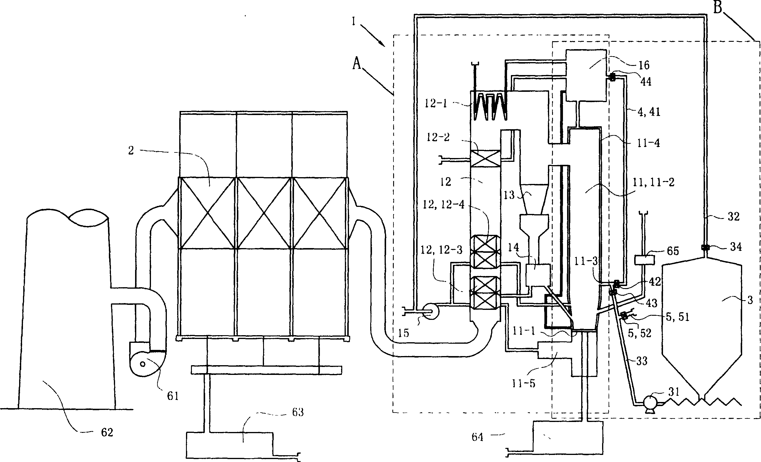
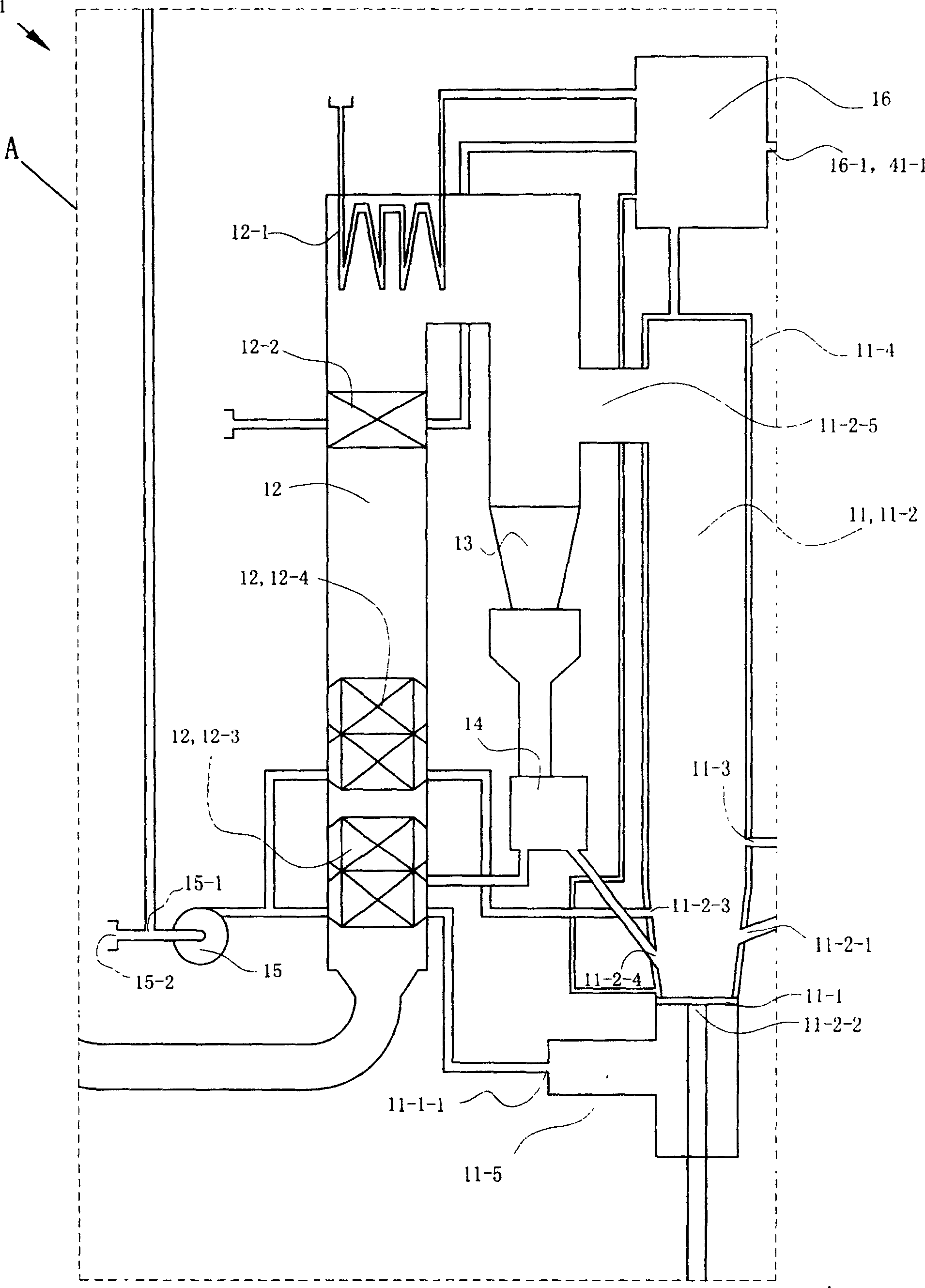
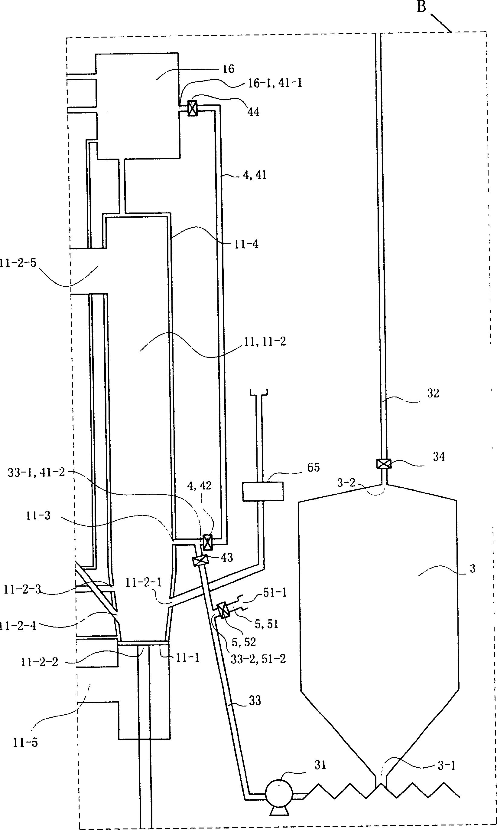
[0028] (Example 1, sludge incineration treatment system)

[0029] See Figure 1 to Figure 3 , the sludge incineration treatment system in this embodiment has a circulating fluidized bed boiler 1, a dust collector (the dust collector 2 is an electrostatic precipitator, and its model is FAA3×35M-44-55A2, purchased from Shanghai Metallurgical Mining Machinery Factory ) 2 and sludge storage room 3; circulating fluidized bed boiler 1 includes boiler main body 11, tail shaft flue 12, separator (the separator is a cyclone separator) 13, feeder 14, primary fan 15 and steam Package 16; the primary air blower 15 is provided with a first air inlet 15-1 for inputting the polluted gas produced in the storage process of the dewatered sludge and a second air inlet 15-2 for inputting air, and the tail shaft flue 12 is provided with The superheater 12-1, the economizer 12-2, the second air preheater 12-4 and the first air preheater 12-3 are arranged in sequence from top to bottom; the boiler ...

Embodiment 2

[0034] (Embodiment 2, sludge incineration treatment method)

[0035] See Figure 1 to Figure 3 , The sludge incineration treatment system used in this example is the sludge incineration treatment system in Example 1.


PUM


Abstract

The invention relates a treatment method and system for burning sludge, which comprises: conveying the dewatered sludge in moisture percentage of 75-85 % into a combustion chamber of a circulating fluidized bed, and conveying the contaminated gas produced in storing process into the combustion chamber of the circulating fluidized bed, burning the dewatered sludge, contaminated gas and coal together, the end gas discharges by processing. The system comprises circulating fluidized bed boiler, ash separator and sludge storeroom, conveying the dewatered sludge through a sludge carrier pipe and a sludge spraying cap using a screw pump, emitting the sludge into the combustion chamber of the circulating fluidized bed and burning, conveying the said contaminated gas into the chamber of the circulating fluidized bed too. The system also has a steam purging unit and a water high pressure unit which clean the screw pump, sludge carrier pipe and sludge spraying cap nontiming to prevent the clogging by dewatered sludge.

Description

technical field [0001] The invention relates to a sludge incineration treatment method and a sludge incineration treatment system, in particular to a method and a system for incineration treatment of sludge by using a circulating fluidized bed. Background technique [0002] At present, the treatment methods of the dewatered sludge obtained after the sewage treatment by urban sewage plants mainly include sanitary landfill, land use, and dry incineration. [0003] The sanitary landfill of sludge began in the 1960s and was developed from the perspective of protecting the environment on the basis of traditional burial. It mainly involves strict scientific analysis of the landfill and necessary site protection treatment. So far, it has developed into a relatively mature sludge treatment technology, which has the advantages of low investment, large capacity and quick results. However, there are many problems in the sanitary landfill of municipal sludge: various toxic substances i...

Claims


Application Information

Patent Timeline
IPC IPC(8): C02F11/06F23G7/00
CPCY02W10/40
Inventor 徐建明曹洪涛戴罗平秦晓武吴文伟张永诚陈涛张肖梅朱才明张飞雁马欣蒋汉平
Owner 常州广源热电有限公司
Learn More