Dual-surface metal waveguide measuring method and its device

A double-sided metal and measuring device technology, which is applied in the field of physical measurement, can solve the problems of affecting the accuracy of measurement results, difficult to adjust the distance accurately, and limiting the measurement range, etc., and achieve the effects of short measurement cycle, easy operation and high measurement efficiency

Inactive Publication Date: 2003-02-12
SHANGHAI JIAO TONG UNIV
View PDF1 Cites 27 Cited by
  • Summary
  • Abstract
  • Description
  • Claims
  • Application Information

AI Technical Summary

Problems solved by technology

The advantage of this method is that it avoids the dispersion caused by the dual-wavelength method. However, the distance between the prism and the film to be measured is difficult to adjust accurately, which in turn will have a great impact on the coupling efficiency, resulting in the efficiency of the two couplings. Different, thus affecting the accuracy of the measurement results
Moreover, in order to couple the light from the prism into the thin film material, this method requires that the refractive index of the material to be measured should be smaller than that of the coupling prism, which greatly limits the applicable measurement range of this method.

Method used


Image

  • Dual-surface metal waveguide measuring method and its device
  • Dual-surface metal waveguide measuring method and its device

Examples


Embodiment 1

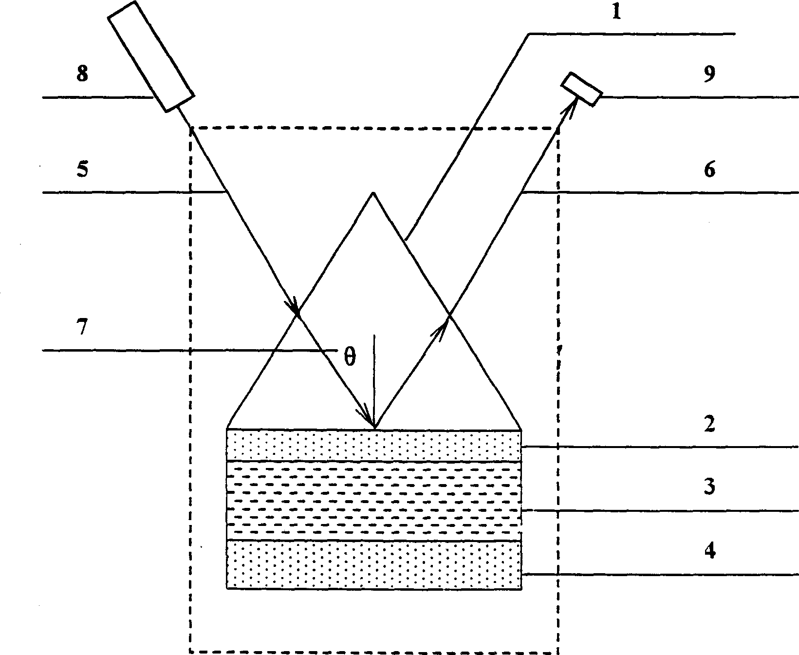
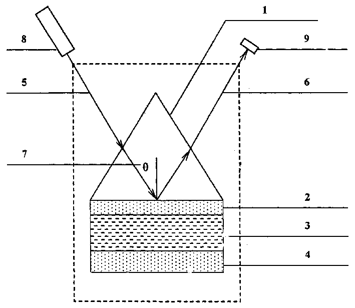
[0035] The first step: the coupling device 1 selects a high-refractive-index equilateral triangular prism (n=1.5), adopts the sputtering method to plate a metal film layer on the bottom surface of the prism and the substrate material, and then puts the two film layers together, and in between A thin layer of air is left to form a double-sided metal waveguide structure. The thickness of the upper metal film 2 is 34nm, the film 3 to be tested is air, the actual value of the thickness is 5μm, and the actual value of the refractive index is 1.0 (dielectric coefficient is 1.0). The metal film 4 has a thickness of 300nm, and the metal is gold (ε=-14.4+i1.22 at a wavelength of 690.0nm);

[0036] The second step: select the incident laser 5 with a wavelength of 690.0nm, the incident light is a transverse magnetic wave (TM mode), and the incident angle 7 is scanned between 0 and 90 degrees;

[0037] Step 3: Receive and measure the light intensity of the laser beam 6 reflected from the ...

Embodiment 2

[0050] The first step: the coupling device 1 selects a high refractive index equilateral rutile prism (n=2.8), and adopts sputtering method to form a double-sided metal waveguide structure on both sides of the film to be tested. The thickness of the upper metal film 2 is 48nm, and the film to be tested 3 It is lithium niobate, the actual value of the thickness is 0.5 μm, the actual value of the refractive index is 2.22 (dielectric coefficient is 4.9284), and the thickness of the lower metal film 4 is 300 nm. The metal is silver (ε=-12.0+i0.4 at a wavelength of 560.0 nm).

[0051] The second step: select the incident laser wavelength 5 to be 560.0nm, the incident light is a transverse magnetic wave (TM mode), and the incident angle 7 is scanned between 0 and 90 degrees;

[0052] Step 3: Receive and measure the light intensity of the laser beam 6 reflected from the bottom surface of the prism on the other side of the prism. The minimum value of the reflected light intensity is t...

Embodiment 3

[0065] Step 1: This example does not use the coupling device 1, but uses the air direct coupling method to excite the guided mode (n=1.0), and uses the sputtering method to form a double-sided metal waveguide structure on both sides of the film to be tested, and the thickness of the upper metal film 2 34nm, the real value of the thickness of the film 3 to be measured is 1000 μm, the real value of the refractive index is 1.673 (dielectric coefficient is 2.8), the thickness of the lower metal film 4 is 300nm, and the metal adopts gold (ε=-34.5+i under the wavelength of 890.0nm .47).

[0066] The second step: select the incident laser 5 with a wavelength of 890.0nm, the incident light is a transverse magnetic wave (TM mode), and the incident angle 7 is scanned between 0 and 90 degrees;

[0067] Step 3: Receive and measure the light intensity of the laser beam 6 reflected from the bottom surface of the prism on the other side of the prism. The minimum value of the reflected light ...


PUM

PropertyMeasurementUnit
Thicknessaaaaaaaaaa
Thicknessaaaaaaaaaa
Thicknessaaaaaaaaaa

Abstract

A device for measuring dual-surface metal waveguide is composed of a coupler, an upper metal membrane, the film layer to be measured, and a lower metal membrane. The film layer to be measured and the two metal membranes are of dual-surface metal waveguide structure with the upper and lower metal membranes as upper and lower cover layers for wave guide, and so the light is mainly transmitted in the film layer to be measured. Its method includes such steps as preparing the device by evaporation plating, sputtering, or other methods, selecting the wavelength, incident angle and polarizing mode of laser, receiving and recording the laser intensity, changing the incident angles to obtain the laser intensity-incident angle curve, finding out the resonant angle, width and depth of absorption peak, and calculating refractivity and thickness of the film material.

Description

technical field [0001] The invention relates to a measuring method and its device, in particular to a double-sided metal waveguide measuring method and its device, belonging to the field of physical measurement. Background technique [0002] In the past two decades, with the development of laser technology, especially the development of integrated optoelectronics technology, the measurement of optical properties and thickness of materials and the research and application of optical waveguide characterization technology have made great progress. Among them, the dual-wavelength method has been put into practice, and there are many reports on it. After literature search, it was found that the U.S. Patent No. 5034617, the patent name is: method and device for measuring film thickness and refractive index. This patent proposes a method for measuring optical film thickness. In this method, a certain wavelength λ1 is selected The laser beam is incident on the substrate material co...

Claims


Application Information

Patent Timeline
IPC IPC(8): G01B11/06G01N21/55G01N21/59G01N21/86
Inventor 曹庄琪陈洸沈启舜李红根周峰
Owner SHANGHAI JIAO TONG UNIV
Why Eureka
Try Eureka