Catalyst surface-characteristic comprehensive measuring device and application thereof

A technology of surface properties and catalysts, applied in the direction of instruments, measuring devices, scientific instruments, etc., can solve problems such as difficulties, time-consuming, and large errors, and achieve the effect of simple structure, convenient operation, and small errors

Inactive Publication Date: 2004-04-21
SHANGHAI NORMAL UNIVERSITY
View PDF0 Cites 25 Cited by
  • Summary
  • Abstract
  • Description
  • Claims
  • Application Information

AI Technical Summary

Problems solved by technology

Traditional testing methods are time-consuming, laborious, and have large

Method used


Image

  • Catalyst surface-characteristic comprehensive measuring device and application thereof
  • Catalyst surface-characteristic comprehensive measuring device and application thereof
  • Catalyst surface-characteristic comprehensive measuring device and application thereof

Examples


Embodiment 1

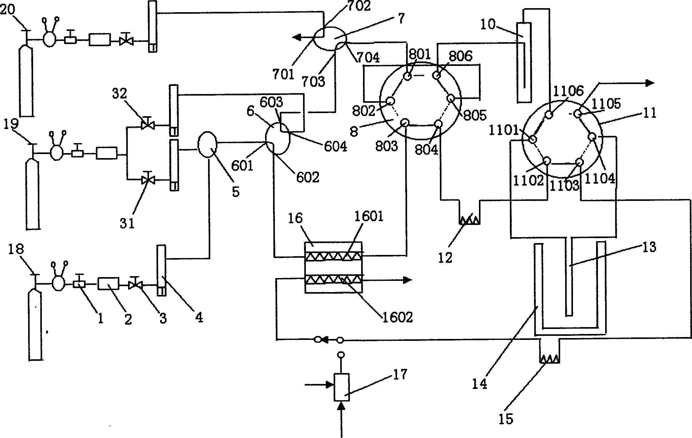
[0189] use as figure 1 The apparatus shown, performs TPR tests on Cu-containing hydrotalcite-like catalysts.

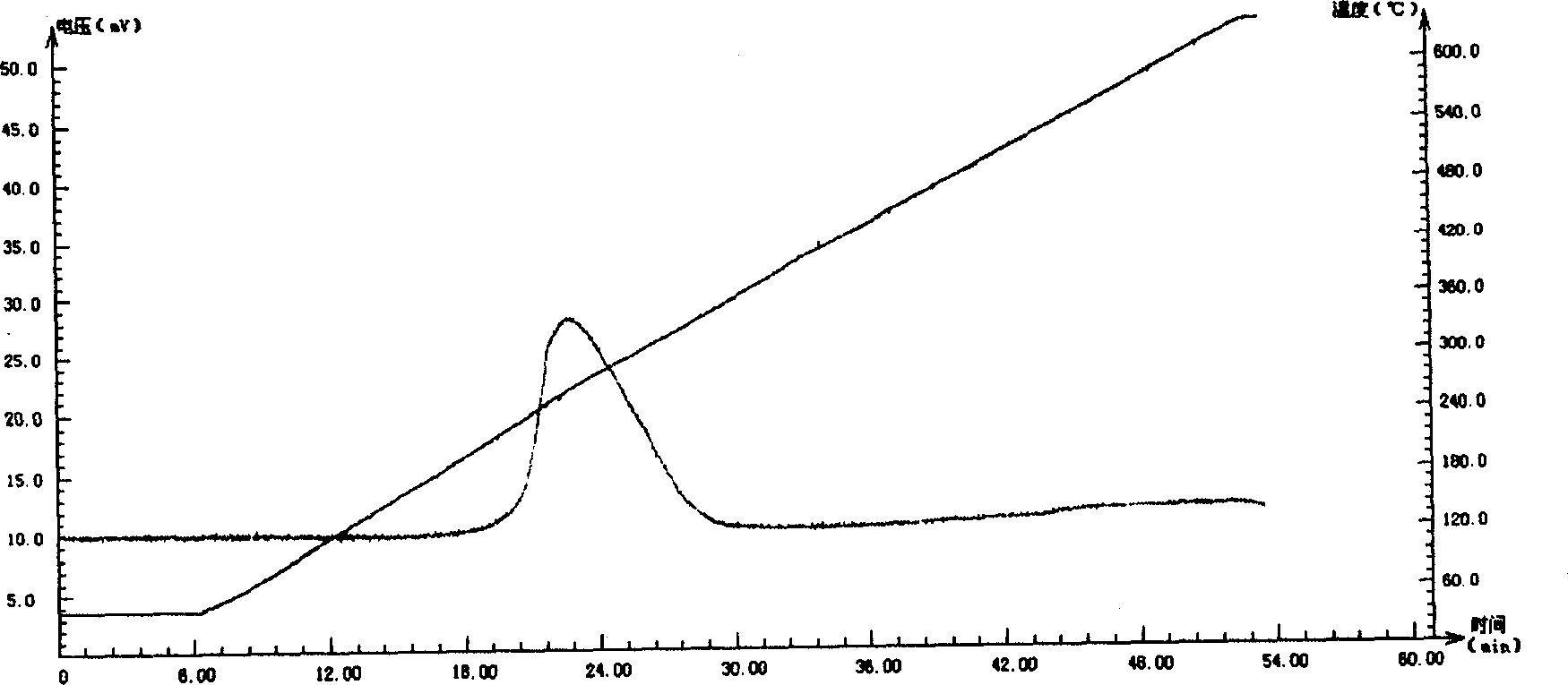
[0190] 1). Take 0.2g of Cu-containing hydrotalcite that has been calcined, and use reducing gas H 2 account for H 2 -5% of He gas mixture (total flow rate of gas mixture: 50ml / min);

[0191] 2). After the baseline becomes stable, perform temperature-programmed reduction at a heating rate of 10°C / min. Its TPR spectrum is figure 2 .

[0192] As a comparison, the TPR test of CuO was done.

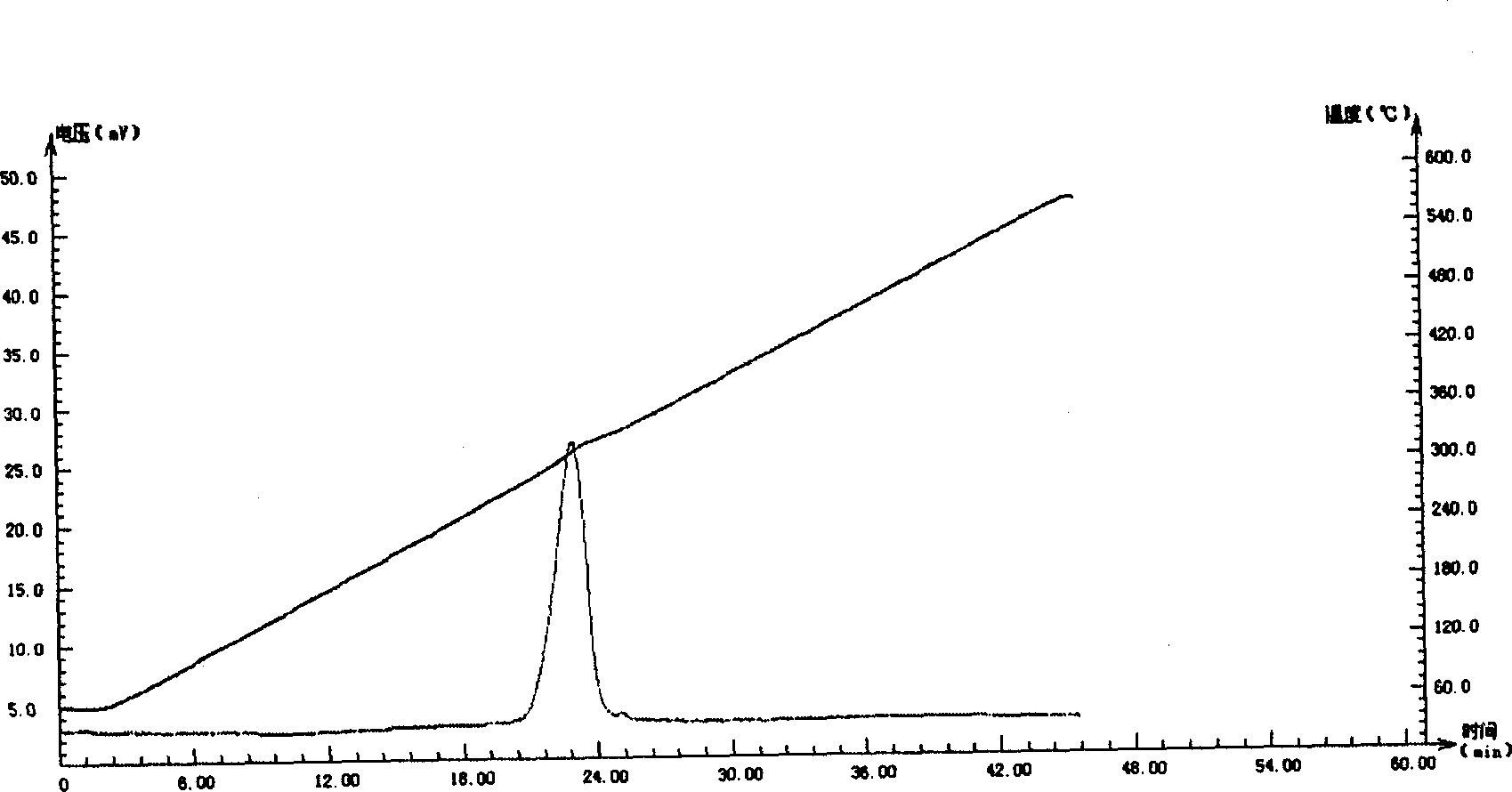
[0193] 1). Take 0.04g of dry CuO, reducing gas H 2 account for H 2 -5% of He gas mixture (total flow rate of gas mixture: 50ml / min);

[0194] 2). After the baseline becomes stable, perform temperature-programmed reduction at a heating rate of 10°C / min. Its TPR spectrum is image 3 .

[0195] It can be seen from the figure that the TPR spectra of the Cu-containing hydrotalcite-like catalyst and CuO both have only one spectrum peak. The highest peak temperature of the former...

Embodiment 2

[0197] use as figure 1 The instrument shown, performs TPD testing on iron oxide catalysts.

[0198] 1) Iron trioxide catalyst 0.8g, reducing gas H 2 account for H 2 -5% of He mixed gas (total flow rate of mixed gas: 50ml / min); reduce at 450°C for 2h; then, close He, 2 (30ml / min), cool to room temperature (27°C).

[0199] 2) Close H 2 , turn on He (30ml / min) to purge to remove reversibly adsorbed H 2 , after the baseline becomes stable, conduct H at a rate of 25°C / min 2 desorption.

[0200] The direction of the peak can be adjusted by selecting the "positive\negative" switch of the detector. See TPD Spectrum Figure 4 .

[0201] Depend on Figure 4 It can be seen that the catalyst has only one broadened desorption peak, indicating that the energy distribution on the catalyst surface is relatively uniform; the highest peak temperature is 296 ° C, indicating that the H absorption 2 The active center is medium strength.

Embodiment 3

[0203] use as figure 1 The instrument shown, performs TPD tests on molybdenum-containing molecular sieve catalysts.

[0204] 1) Take 0.2 g of the catalyst that has been calcined at a high temperature, put it into the sample tube, purify it with He at 400 ° C for 1 h, and then cool it to 120 ° C. After the temperature is constant, use He to pass the NH 3 Vapor is introduced into the sample tube for adsorption.

[0205] 2) He (40ml / min) as carrier gas, purge to remove reversibly adsorbed NH 3 , after the baseline stabilized, the temperature-programmed desorption was performed at a rate of 10°C / min. See TPD Spectrum Figure 5 .

[0206] The spectrum shows that there are at least three kinds of adsorption centers on the surface of the catalyst (the highest peak temperature: 242°C, 325°C, 472°C), and the energy distribution on the surface is uneven, and the weak acid centers are the main ones.


PUM


Abstract

The instrument comprises carrier gas inlet, working gas inlet, other gas inlet, gas flow meter, mixer, the first and the second four-way valve, the first and the second six-way valve, saturator, heating furnace with programmed control temperature, sample tube with internal-inserted thermocouple, heat conductive pool, cold-trap, chromatographic column, hydrogen flame detector sampling and displaying of computer and spectrogram printing. The instrument with above devices can apply techniques of programmed temperature for reduction de-addendum, surface reaction, oxidation and decomposition as well as H2-O2 titration to carry on surface performance test for catalyst and to obtain spectrogram for each abovesaid performance of the catalyst.

Description

technical field [0001] The invention relates to a test instrument, in particular to a catalyst surface property comprehensive measuring instrument and its application. technical background [0002] In the study of heterogeneous catalysis, due to the complexity of the catalyst's own composition, structure and related reaction kinetics system, it is very difficult to explain the catalytic activity and mechanism, thus hindering the optimal analysis of specific chemical processes. Catalyst selection. [0003] Although there are many characterization methods for catalysts, such as X-ray powder diffraction, electron microscopy, photoelectron spectroscopy, infrared spectroscopy, thermal analysis, etc., none of these techniques can give the properties of catalysts under actual working conditions. [0004] General physical methods, in addition to their respective limitations in instruments and theory, if combined with the adsorption process, can often profoundly explain the adsorpti...

Claims


Application Information

Patent Timeline
IPC IPC(8): G01N30/02G01N30/06G01N30/66G01N30/88G01N35/00
Inventor 杨良准
Owner SHANGHAI NORMAL UNIVERSITY
Why Eureka
Try Eureka