

Device for pulling monocrystals
A single crystal and heater technology, applied in the direction of single crystal growth, single crystal growth, post-processing equipment, etc., to achieve the effects of improving uniformity, reducing carbon pollution, and extending service life
- Summary
- Abstract
- Description
- Claims
- Application Information
AI Technical Summary
Problems solved by technology
Method used
Image

Examples
Embodiment 1
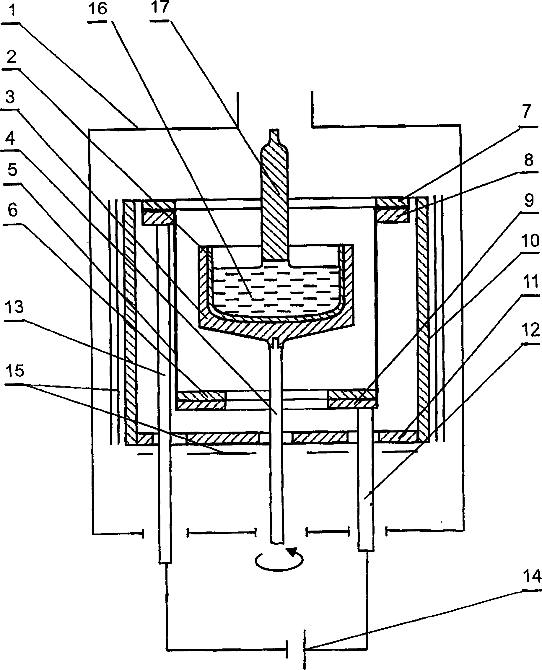
[0048] The process is carried out in a vacuum chamber 1 . use as figure 1 The device shown consists of a carbon containing 3 x 10 15 cm -3 And oxygen 2×10 16 cm -3 A boron-doped silicon single crystal with a diameter of 150mm was grown from polycrystalline silicon. In subsequent examples, the same material was used. A quartz crucible 2 with an outer diameter of 356 mm in a support 3 installed on a pole 4 is used, and 30 kg of polysilicon is loaded in the crucible.
[0049] The heater 5 was made by braiding carbon fibers into a cylinder with a thickness of 0.6 mm (0.0006 m) using graphite as a mandrel. Fix the end of the cylinder through the flange to form a horizontal plane, and clamp it with contact rings 6, 7, 8, 9. A thin layer of silicon nitride is coated on the inner surface of the cylinder in heater 5 (after removal of the mandrel). The operation method of coating this layer is by SiCl at 1300°C 4 -NH 3 -H 2 Formed by precipitation of the gas mixture, the cons...
Embodiment 2
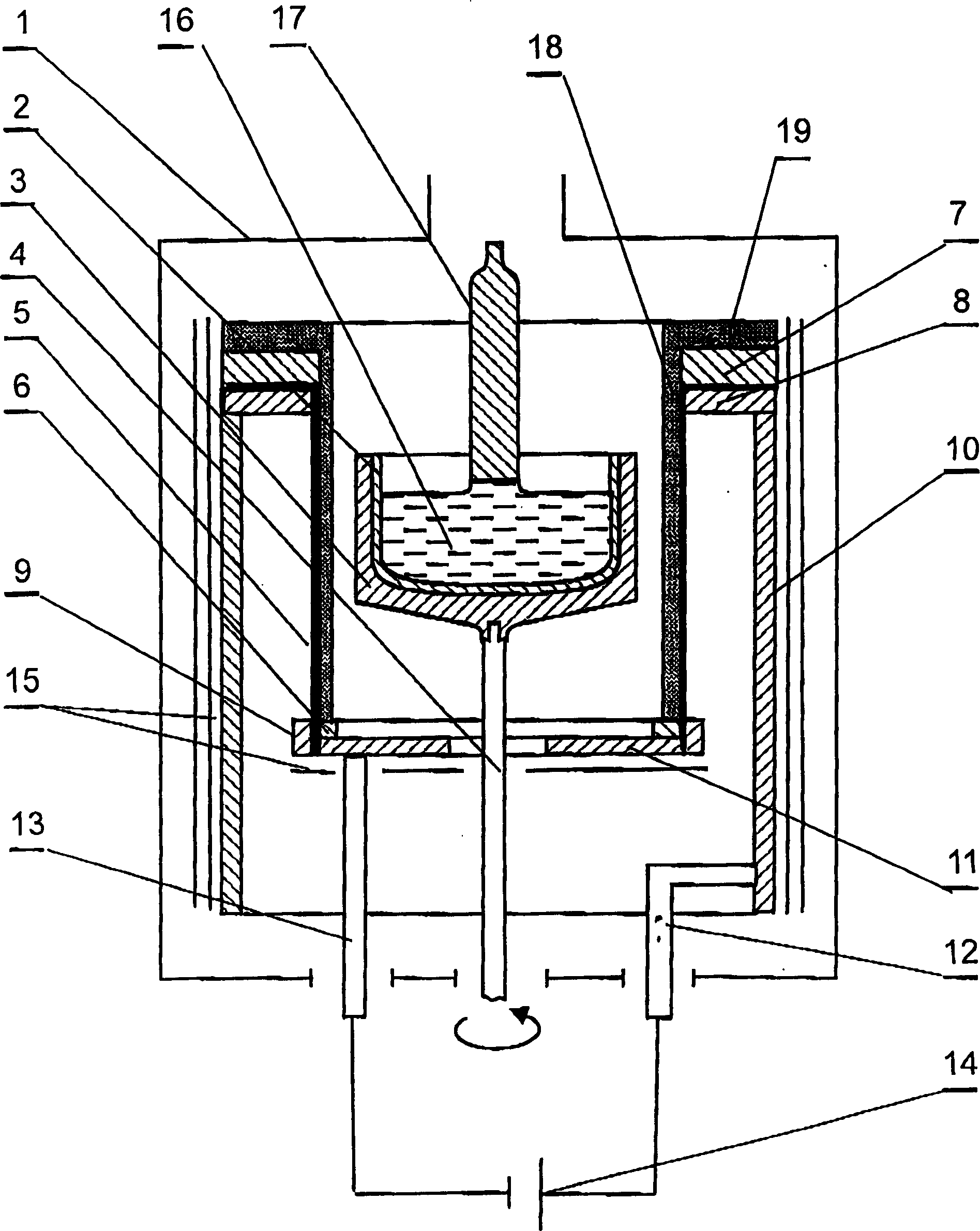
[0057] use as figure 2 The setup shown pulls a single crystal. Containing carbon 3×10 15 cm -3 A boron-doped silicon single crystal with a diameter of 150mm was grown from polycrystalline silicon. A quartz crucible with an outer diameter of 356 mm is used, and the feeding amount is 30 kg. The housings 10 , 11 are made of graphite and are electrically insulated from the vacuum chamber 1 . The heater 5 is made by winding two layers of "Ural" type carbon fabric on a graphite mandrel. Then, the upper end face of the cylindrical heater is cut into a petal shape, clamped between two rings 7 and 8 made of carbon material (the length of the petal is equal to the width of the rings 7 and 8), and the lower end face is placed on the ring 6 and 9 are clamped. Vertical seams are stitched with carbon fiber. After removal of the mandrel, the heater and insulated housing / wires were sealed with pyrolytic graphite using known procedures at a temperature of 1050°C, a pressure of 28 mmHg,...
Embodiment 3
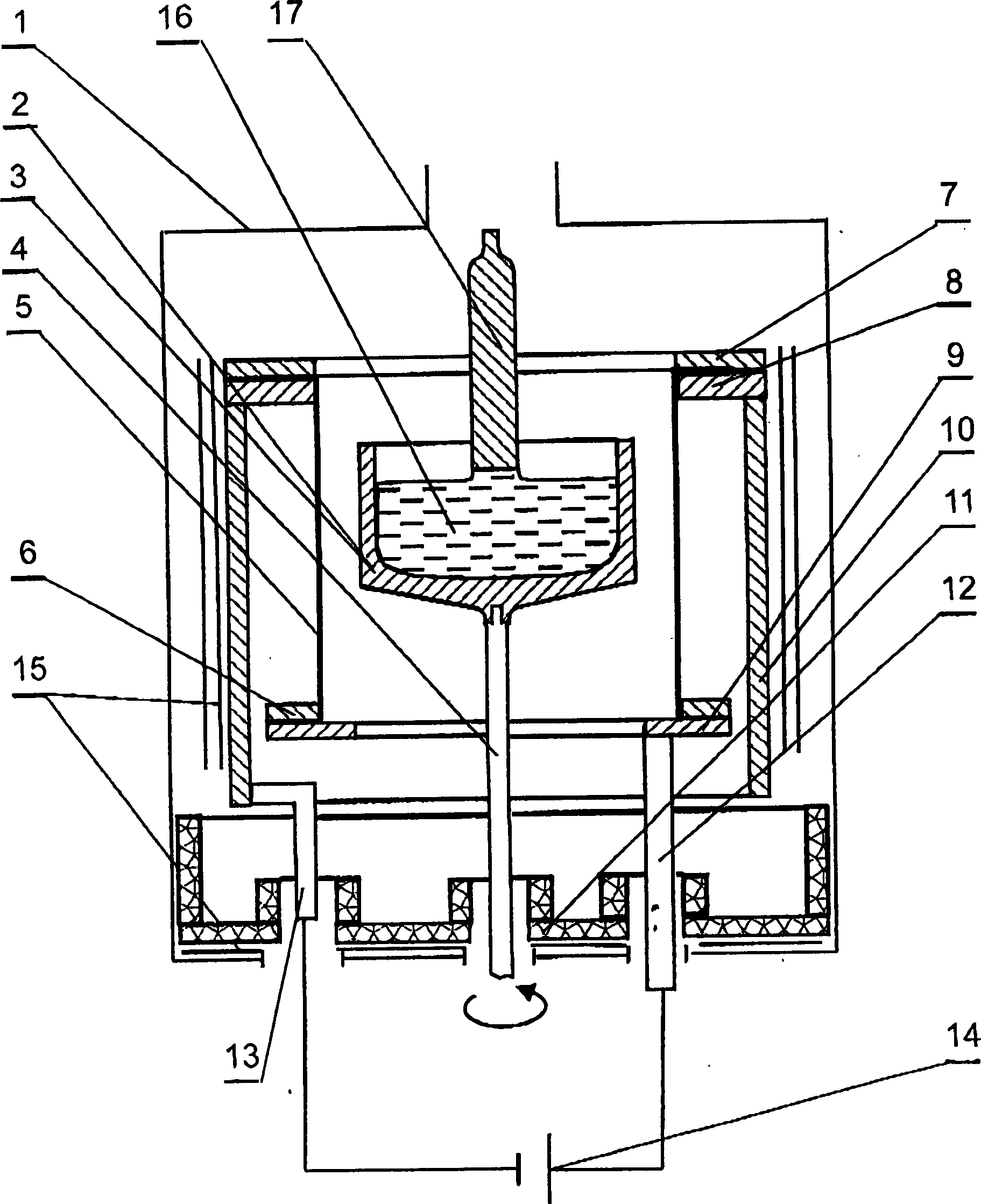
[0065] When growing a silicon single crystal with a diameter of 150 mm from a polysilicon charge with a mass of 30 kg, crucible 2 and holder 3 with an outer diameter of 370 mm and made of silicon nitride integrated with each other can be used. The device consists of a side housing / wire 10 ( image 3 ), the upper part is connected with a ring 8 made of graphite, and the bottom part is connected with an electric wire 13. Wires 12 are connected to a pair of graphite rings 6 and 9 at the bottom. The bottom housing 11 is not connected to an electric circuit, and is installed at the bottom of the vacuum chamber 1 . The canister heater 5 is made of thermally expanded rolled graphite. The wall thickness of the heater is 2mm (0.002m). Cut the end face of the cylinder into a petal shape and bend it, and clamp and fix it with rings 7, 8 and 6, 9 respectively. A thin layer of silicon nitride is coated on the inner and outer surfaces of the heater. The housing 10 and struts 4 are made...
PUM
| Property | Measurement | Unit |
|---|---|---|
| thickness | aaaaa | aaaaa |
| density | aaaaa | aaaaa |
| melting point | aaaaa | aaaaa |
Abstract
Description
Claims
Application Information