Laser interference photo etching method adopting holographic optical elements and photo etching system

A holographic optical element and laser interference lithography technology, which is applied in the improvement field of laser interference lithography system, can solve the problems of large beam splitter and poor adaptability of patterns of different periods, and achieve improved signal-to-noise ratio, light weight, and reduced Effect of System Fees

Inactive Publication Date: 2005-11-02
INST OF OPTICS & ELECTRONICS - CHINESE ACAD OF SCI
View PDF0 Cites 17 Cited by
  • Summary
  • Abstract
  • Description
  • Claims
  • Application Information

AI Technical Summary

Problems solved by technology

The traditional beam splitters such as prisms, variable density disks, and semi-reflective mirrors are large and heavy, and have poor adaptability to generating different periodic patterns.

Method used


Image

  • Laser interference photo etching method adopting holographic optical elements and photo etching system
  • Laser interference photo etching method adopting holographic optical elements and photo etching system
  • Laser interference photo etching method adopting holographic optical elements and photo etching system

Examples


Embodiment Construction

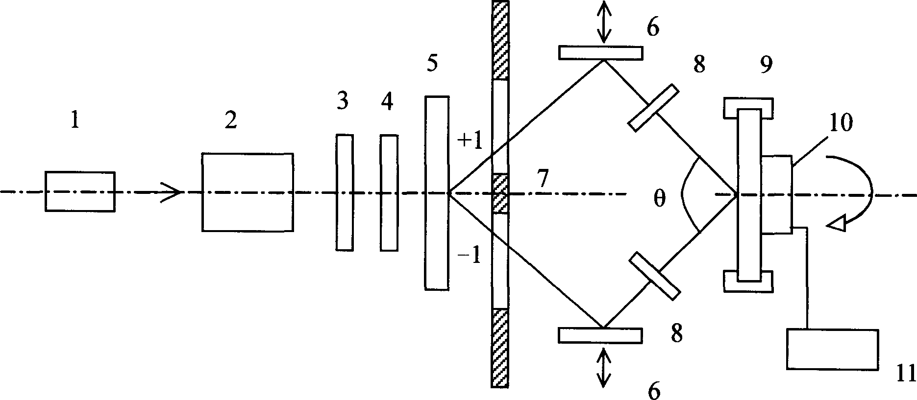
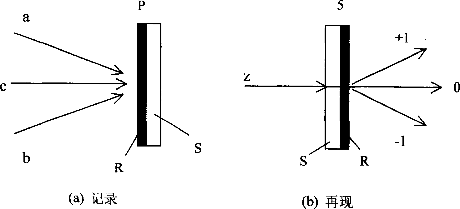
[0015] Such as figure 1 As shown, the present invention includes a laser 1, a beam expander collimator 2, a timing shutter 3, a variable density filter 4, a holographic optical element 5, a total reflection mirror 6, an adjustable diaphragm 7, an optical attenuator 8, a base Sheet and its holder 9, electric control rotation mechanism 10 and control power supply 11. The laser light emitted by the laser 1 is incident on the holographic optical element 5 after passing through the beam expander collimator 2, the timing shutter 3, and the variable density filter 4, and the beams (+1) and (- 1) Pass through the adjustable diaphragm 7, pass through the total reflection mirror 6 and the light attenuator 8, intersect at an angle θ and overlap the resist substrate 9, and expose the photoresist coated on the substrate 9 After exposure, after developing, baking and other treatments, a one-dimensional grating pattern can be obtained. After the first exposure, before processing such as de...


PUM


Abstract

The laser interference photo-etching method with holographic optical element is characterized in that: use holographic optical element as beam amplitude division element to divide the laser beam to two beams of almost equal strength and angle divided; reflect to make them intersect; on the intersect overlap area, expose the resister basal plate to produce high resolution grating, form minuteness interference image; holographic optical element is element that can produce tri-beam, quad-beam, or quint-beam, or holographic image produced by computer, or diffraction optic element; laser interference photo-etching system realized aforementioned method comprises a laser of ª™-wave, beam expand collimating device, timer shutter, variable density neutral color filter, holographic optical element, adjustable diaphragm, holophote, optical attenuator, basal plate and electric control roller. As the preparation of holographic optical element is easy, with light weight, and can made with low cost according to different angle to adjust different needs, this invention can decrease size, weight and cost of the system, of far reaching importance and application future.

Description

technical field [0001] The invention relates to a laser interference lithography method using a holographic optical element and a lithography system thereof, which belongs to the improvement of the laser interference lithography system for generating periodic pattern arrays. technical background [0002] A general laser interference lithography system consists of a wavelength λ laser, a beam expander collimator, a prism beam splitter or a variable density disk beam splitter, or a transflective beam splitter and a resist substrate, etc. The resist substrate was rotated using a manual rotation device. Literature Saleem H.Zhidi et.al., Interferometriclithography exposure tool for 180nm structures, SPIE Proc.Vol.3048, 1997:248-254 and A.Femandez et.al., Use of interference lithography to patternarrays of submicron resist structures for field Laser interference lithography is introduced in emission flat panel displays, J.Vac.Sci.Technol.B15(3), 1997:729-735. However, the litera...

Claims


Application Information

Patent Timeline
Patent Type & Authority Applications(China)
IPC IPC(8): G03F7/20
Inventor 张锦冯伯儒
Owner INST OF OPTICS & ELECTRONICS - CHINESE ACAD OF SCI
Why Eureka
Try Eureka