
Light-emitting element device, light-receiving element device, optical device, fluoride crystals, production method of fluoride crystals, and crucible

A technology for light-receiving elements and light-emitting elements, applied in optical elements, chemical instruments and methods, optics, etc., can solve the problems of reduced luminous efficiency, high light energy, reduced reliability, etc., and achieves improved decomposition resistance, transparent The effect of good light rate and improved reliability

Inactive Publication Date: 2006-03-29
View PDF1 Cites 9 Cited by
  • Summary
  • Abstract
  • Description
  • Claims
  • Application Information

AI Technical Summary

Problems solved by technology

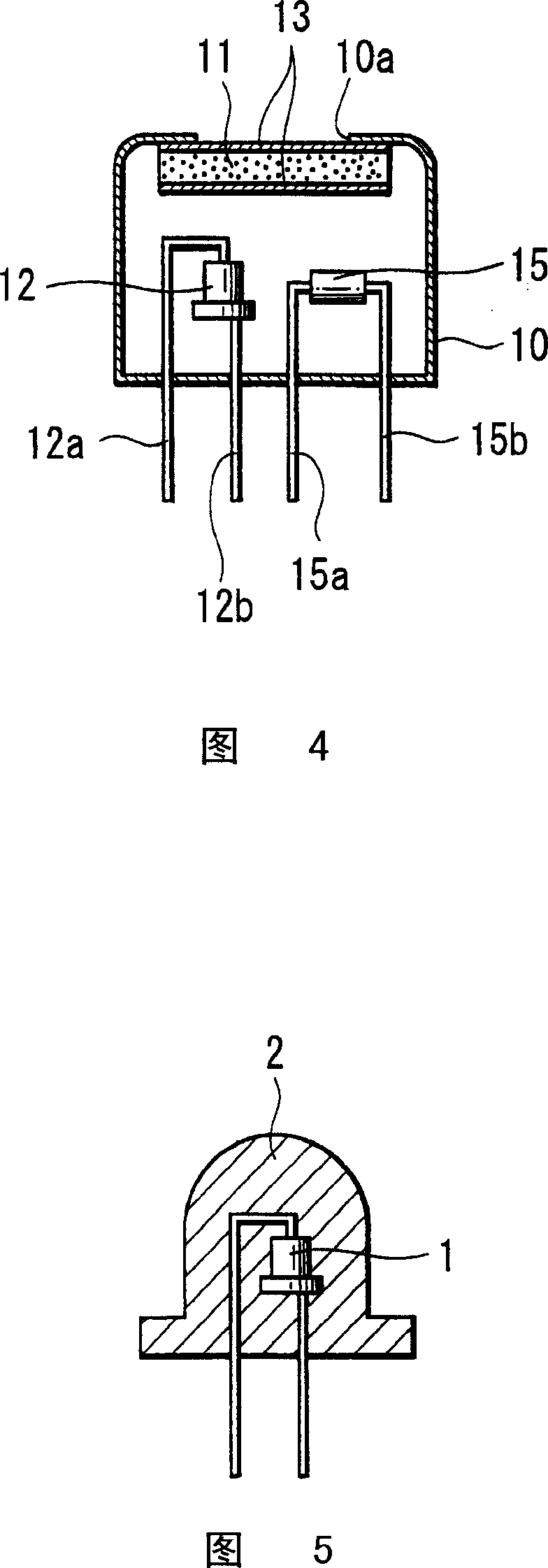
[0006] However, the short-wavelength light-emitting element 1 such as the ultraviolet light-emitting element and the blue light-emitting element has high energy of light, and the bond of the epoxy resin 2 covering the short-wavelength light-emitting element 1 is decomposed, and the transparency disappears.
As a result, in the light-emitting element device using this short-wavelength light-emitting element 1 , problems such as a significant decrease in luminous efficiency occurred as the use progressed.
[0007] Moreover, in the light-emitting element device using the short-wavelength light-emitting element 1, in order to change the wavelength, elements such as phosphorus are mixed in the coated epoxy resin 2 to make a light-emitting element device that emits, for example, yellow light. The following disadvantages are found, that is, due to the energy of the short-wavelength light, the epoxy resin 2 is decomposed as the use proceeds, and the luminous efficiency is reduced, and at the same time, the phosphorus atoms are directly adhered to the wiring of the diode constituting the short-wavelength light-emitting element 1. surface, corroding the wiring, significantly reducing reliability

Method used


Image

  • Light-emitting element device, light-receiving element device, optical device, fluoride crystals, production method of fluoride crystals, and crucible
  • Light-emitting element device, light-receiving element device, optical device, fluoride crystals, production method of fluoride crystals, and crucible
  • Light-emitting element device, light-receiving element device, optical device, fluoride crystals, production method of fluoride crystals, and crucible

Examples


Embodiment 1

[0108] Embodiment 1 (add the CaF of Ti 2 )

[0109] Manufacture of titanium-added calcium fluoride.

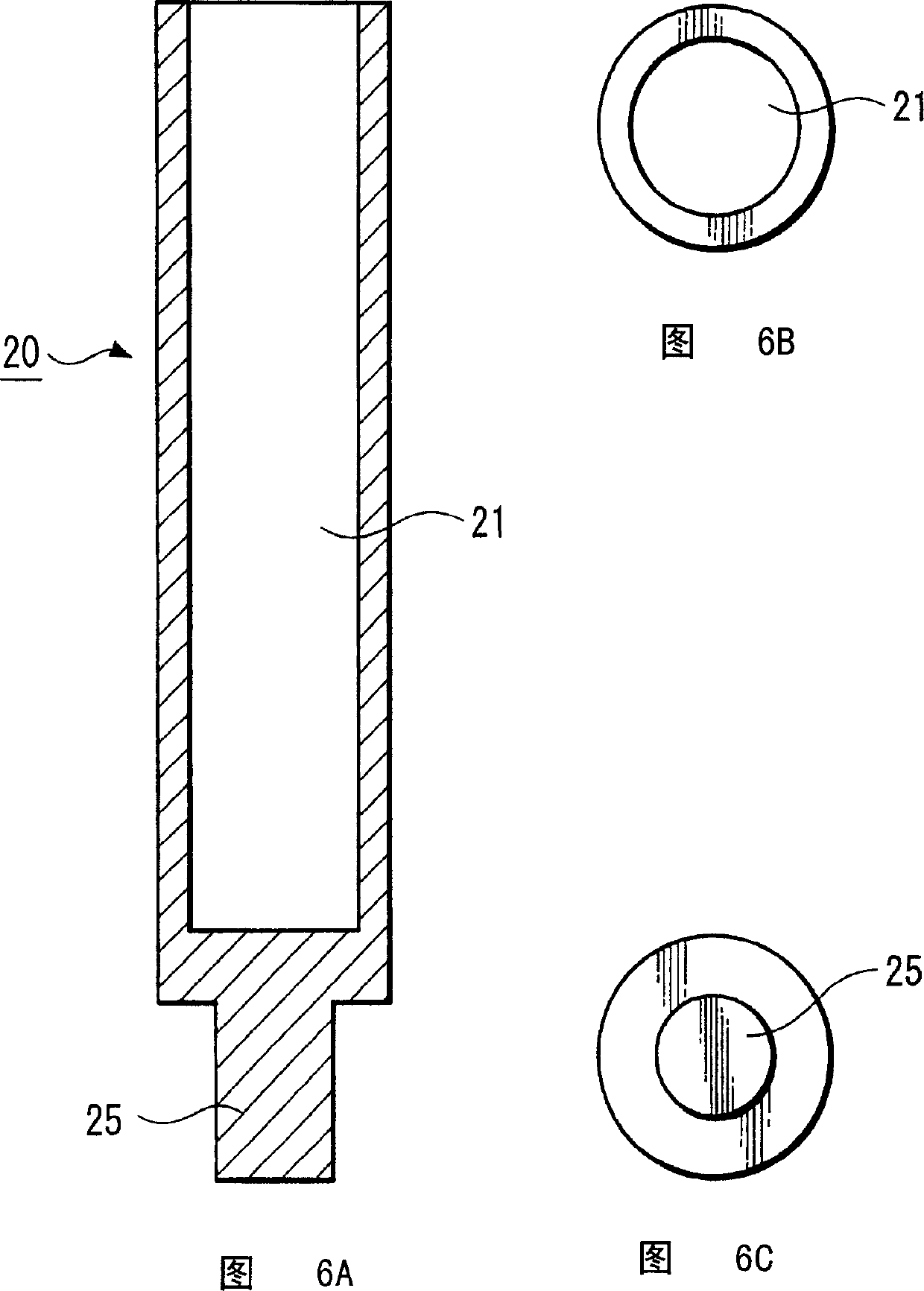
[0110] A method for producing titanium-added calcium fluoride will be described. Figures 6A, 6B, and 6C show graphite crucibles for producing fluoride crystals of the present invention. The diameter of the cavity portion 21 is 1 inch (2.54 cm). Fill the graphite crucible with CaF 2 Raw material powder, which is inserted into a vertical Bridgman furnace. Add CaF to graphite crucible 2 0.1 mol% Ti was added to the raw material to form crystals. When determining the crystal orientation, place the seed crystal on the bottom of the crucible. When the crystal orientation is not determined, it is not necessary to use a seed crystal. After that, a 1×10 -6 The vacuum is around Torr, and the electric furnace is heated up to 1450°C while maintaining the vacuum. In this state, it is kept warm for about 2 hours to melt and stabilize the internal raw materials according to the temp...

Embodiment 2

[0115] (Add TiF 3 CaF 2 )

[0116] Manufacture of calcium fluoride added with titanium fluoride.

[0117] Adding CaF to the graphite crucible 2 Add 0.1mol% TiF as raw material 3 , other are identical with embodiment 1 except this.

[0118] In addition, calcium fluoride to which 2 mol% of titanium fluoride was added and calcium fluoride to which 2 mol% of titanium fluoride+0.5 mol% of zinc fluoride were added were produced by the same method as in Example 1.

Embodiment 3

[0120] (Add SrF 2 CaF 2 )

[0121] Manufacture of calcium fluoride doped with strontium fluoride.

[0122] Adding CaF to the graphite crucible 2 Add 0.1mol% SrF as raw material 2 , other are identical with embodiment 1 except this.

[0123] In addition, calcium fluoride added with 0.2 mol%, 0.6 mol%, or 2 mol% of strontium fluoride, and calcium fluoride added with 2 mol% of strontium fluoride + 0.5 mol% of zinc fluoride were produced by the same method as in Example 1. .


PUM


Abstract

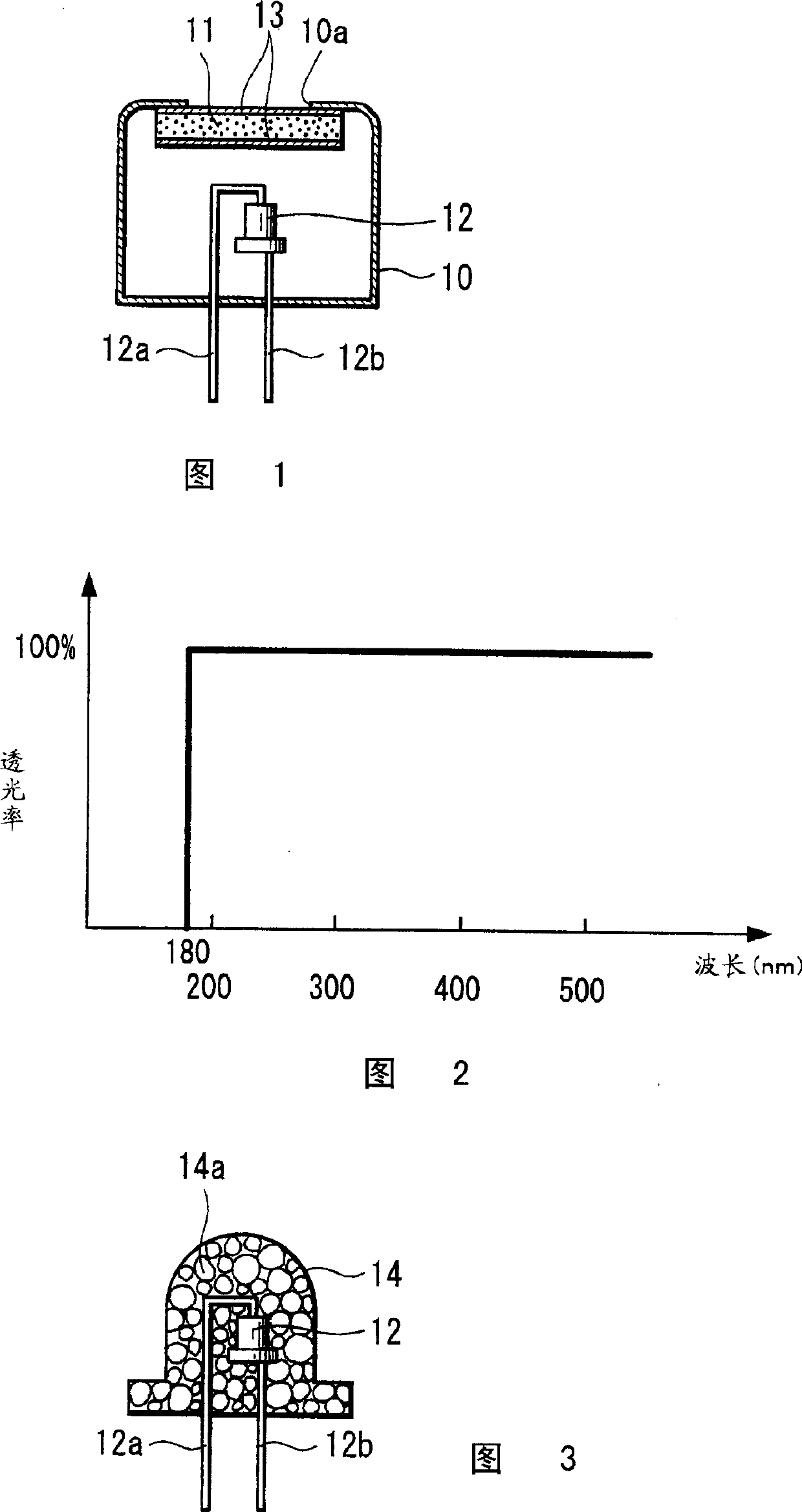
A short-wavelength light-emitting element such as an ultraviolet light-emitting element or blue light-emitting element is arranged in a container which has a window with a window board formed of calcium fluoride crystals. Fluoride crystals are ones which contain either metal or metal halide, or both of them. In a production method of fluoride crystals in which the cavity of a crucible is filled with raw material powder and this crucible is heated in a vertical Bridgman furnace, a production method of fluoride crystals of the present invention is the one in which the shortest diameter of a cross section of the cavity of the crucible is small. In a crucible, whose cavity is filled with raw material powder, heated in a vertical Bridgman furnace to produce fluoride crystals, a crucible is the one in which the shortest diameter of a section of the cavity is small.

Description

technical field [0001] The present invention relates to a light-emitting element device using a short-wavelength light-emitting element such as an ultraviolet light-emitting element and a blue light-emitting element, a light-receiving element device using a short-wavelength light-receiving element, and an optical device. [0002] The present invention relates to fluoride crystals, a method for producing the fluoride crystals and a crucible for producing the fluoride crystals. Background technique [0003] Conventionally, in a light-emitting element device using a short-wavelength light-emitting element such as an ultraviolet light-emitting element or a blue light-emitting element, as shown in FIG. wavelength light-emitting element 1. [0004] In addition, using short-wavelength light-emitting elements 1 such as ultraviolet light-emitting elements and blue light-emitting elements, visible light is obtained by changing the wavelength. Such a light-emitting element device is m...

Claims


Application Information

Patent Timeline
Patent Type & Authority Applications(China)
IPC IPC(8): H01L33/00H01L31/02H01S5/022G02B1/02C30B29/12C30B29/64H01L31/0232H01L33/32H01L33/44H01L33/48H01L33/50H01L33/56
CPCH01S5/0222H01L33/44H01S5/02296H01L33/483G02B1/02H01L2924/0002H01S5/02257H01L2924/00H01L33/50
Inventor 寺嵨一高西村铃香
Learn More