Electrophoretic display and process for its manufacture

An electrophoresis and electrode layer technology, which is applied in static indicators, electrical recording processes and instruments using photoelectrophoresis, etc., can solve the problems of low effective load of pigment particles, poor scratch resistance, and reduced contrast, and achieve easy handling. Effect

Active Publication Date: 2006-05-17
SIPIX IMAGING INC
View PDF15 Cites 10 Cited by
  • Summary
  • Abstract
  • Description
  • Claims
  • Application Information

AI Technical Summary

Problems solved by technology

Second, microcapsule-based electrophoretic displays have poor scratch resistance due to the thin walls and large particle size of the microcapsules
In order to improve the operational performance of the display, the microcapsules are embedded in a large amount of polymer matrix, but the response time becomes longer due to the larger distance between the two electrodes; moreover, due to the low payload of the pigment particles, the Contrast reduction
Difficulty increasing surface charge density on pigment particles because charge control agents tend to diffuse to the water / oil interface during microcapsule preparation
The low charge density or zeta potential of the pigment particles in the microcapsules also slows down the response
Furthermore, this type of electrophoretic display has lower resolution and addressability for color applications because of the large particle size and wide size distribution of the microcapsules

Method used


Image

  • Electrophoretic display and process for its manufacture
  • Electrophoretic display and process for its manufacture
  • Electrophoretic display and process for its manufacture

Examples


preparation example Construction

[0046] I. Preparation of Microcups

[0047] I(a) Preparation of microcups by compression molding

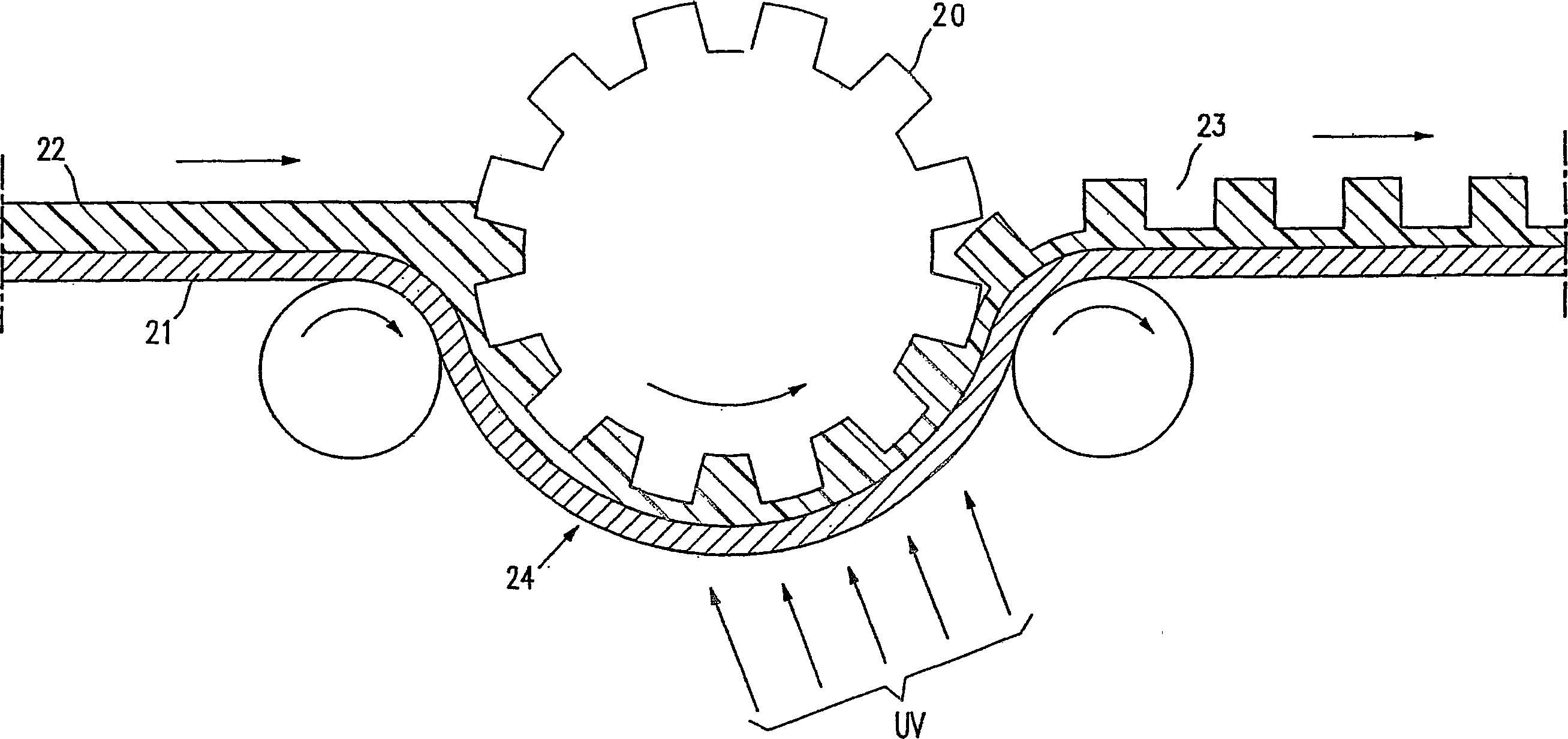
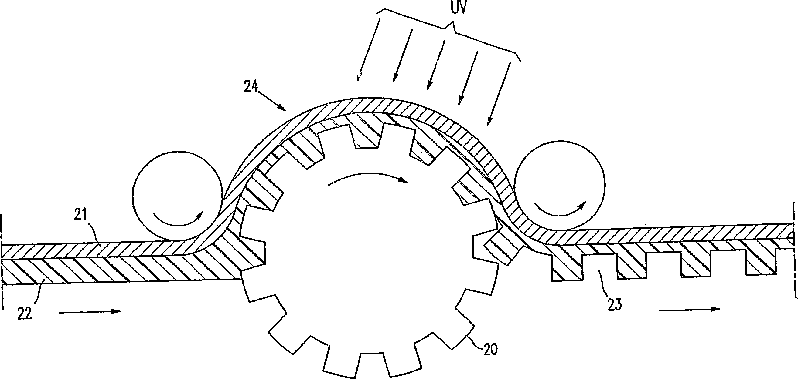
[0048] The process steps are shown in Figure 2a and Figure 2b middle. Punch (20) can be placed on mesh belt (24) ( Figure 2a ) or under the mesh belt ( Figure 2b ). A transparent conductive film (21) is formed on a glass plate or a plastic substrate to make a transparent conductive substrate. A composition (22) comprising a thermoplastic resin, a thermosetting resin, or a precursor thereof is then coated on the conductive film. The thermoplastic or thermosetting precursor layer is embossed with a male die in the form of a roll, plate or belt at a temperature above the glass transition temperature of the thermoplastic or thermosetting precursor layer.

[0049] The thermoplastic or thermoset precursors used to make the microcups can be multifunctional acrylates or methacrylates, vinyl ethers, epoxides and oligomers or polymers thereof, and the like. Most preferred are m...

Embodiment 1

[0129] Fabrication of microcups by micromolding

[0130] The composition shown in Table 1 was coated on Mylar by using a nickel-chromium Bird type (bird type) film applicator with an opening of 3 mils. TM J101 / 200 model. The solvent was evaporated so as to leave a viscous film with a Tg below room temperature.

[0131] Numbering

[0132] A prepatterned stencil from Photo Stencil (Colorado Springs, CO) was used as the punch for micromolding, while Frekote from Henkel TM 700-NC was used as a release agent. The coated film was then embossed at room temperature through a stencil using a pressure roller. Then through Mylar TM film and utilize Loctite Zeta 7410 TM The coating was cured by UV light for about 20 minutes in the exposure device equipped with a metal fluoride lamp with an intensity of 80 mW / cm at 365 nm 2 . The molded film was then demolded to reveal well-defined microcups, as measured by optical profilometry and microscopy ( Figures 4a-4c ), the si...

Embodiment 2

[0134] Preparation of microcups

[0135] Compositions containing solid oligomers, monomers and additives are shown in Table 2. The glass transition temperature of the mixture is also below room temperature. Deposit the sticky coating on Mylar as previously described TM on top of the J101 / 200 template. Molding is performed at 60° C. using a heated press roll or a laminator. High resolution microcups (100-400 dpi) with a well-defined depth range of 5-30 microns were produced.

[0136] Numbering


PUM

PropertyMeasurementUnit
thicknessaaaaaaaaaa
thicknessaaaaaaaaaa
strengthaaaaaaaaaa

Abstract

The present application relates to electrophoretic displays and semi-finished display panels comprising display cells prepared by microcup and top sealing techniques.

Description

technical field [0001] The present invention relates to electrophoretic displays and semi-finished display panels comprising display cells prepared by microcup and top sealing techniques. The partition walls dividing the display units may be opaque. The top surfaces of the partition walls dividing the display units may also be colored, preferably blackened with dyes or pigments. Optionally, the top sealing unit may be covered by a black matrix layer having a black pattern registered to the partition wall. Background technique [0002] An electrophoretic display is a non-emissive device based on the electrophoresis of charged pigment particles suspended in a solvent. Electrophoretic displays were first proposed in 1969. Such displays generally comprise two oppositely disposed plates with electrodes separated by a spacer. Usually, one of the electrodes is transparent. A suspension containing a coloring solvent and charged pigment particles is encapsulated between two plat...

Claims


Application Information

Patent Timeline
Patent Type & Authority Applications(China)
IPC IPC(8): G02B26/00G02F1/167G02F1/1677G02F1/1679G03G17/04G09G3/34
CPCG02F1/167G02F1/1679G02F1/1677
Inventor 梁荣昌张小加臧宏玫钟冶明
Owner SIPIX IMAGING INC
Why Eureka
Try Eureka