Electrical treatment method and appts for soil continuous prodn obstacle
A soil continuous cropping obstacle and electric treatment technology, applied in the field of soil treatment, can solve problems such as no good physical solutions, rampant nematode diseases, and difficult removal of organic acids and harmful substances
- Summary
- Abstract
- Description
- Claims
- Application Information
AI Technical Summary
Problems solved by technology
Method used
Image
Examples
Embodiment 1
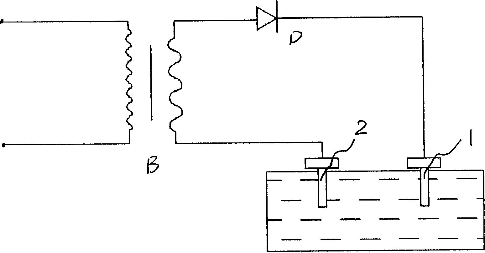
[0033] Equipment used such as figure 1 As shown: there is a transformer B, the positive terminal of the secondary of the transformer B is connected to the electrode 1 through the diode D, and the negative terminal of the transformer B is connected to the electrode 2. The main function of the diode D is rectification, and other rectification circuits can be selected. Such as bridge rectifier circuit and so on. The method of use is also shown in the figure: bury the electrodes 1 and 2 with the electrode handle in the soil with a moisture content of 5-40%. If the moisture content is 28-34%, the electrolysis effect is the best, and the electrodes 1 and 2 are parallel. And corresponding setting, the embedment depth of the electrodes 1 and 2 and the distance between the two electrodes shall be subject to the electrolysis effect, and the soil shall be electrified and electrolyzed. In order to obtain the best electrolysis effect, the embedment depth of the electrodes 1 and 2 in the s...
Embodiment 2
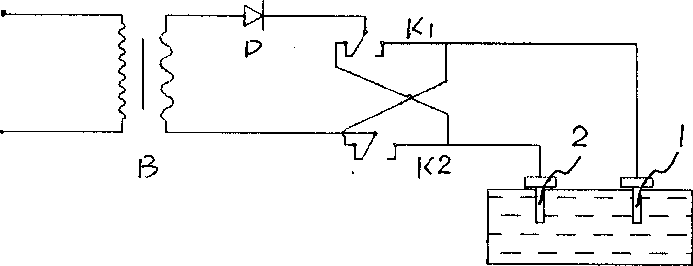
[0035] Equipment used such as figure 2 As shown: there is a transformer B, the positive terminal of the secondary of the transformer B is connected to the electrode 1 through the diode D, the negative terminal of the transformer B is connected to the electrode 2, and the power polarity changeover switch K1 is connected to the electrode 1 and the electrode 2 , K2, switch K1, K2 can choose to manually toggle the switch, or use a cycle timer. After each electrolysis for 3 to 10 minutes, change the electrode polarity so that the soil can be electrolyzed at the positive and negative electrodes in rotation.
[0036] It is also possible to set a pulse modulation integrated block in the circuit to generate a DC pulse current.
Embodiment 3
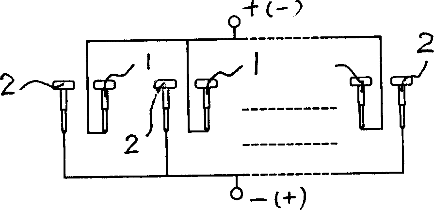
[0038] Others can be with embodiment 1 or embodiment 2, only electrode 1 or electrode 2 are at least two in parallel, and the connection method is as follows image 3 As shown, the specific number can be determined according to the rated power of the entire device. If the voltage is less than 90V and the current is less than 40A, the number of electrodes can be set to 2 to 3, and the longest electrode connection between the electrodes and the power supply should not exceed 70m.
PUM
 Abstract
Description
Claims
Application Information
 - R&D
- Intellectual Property
- Life Sciences
- Materials
- Tech Scout
- Unparalleled Data Quality
- Higher Quality Content
- 60% Fewer Hallucinations
Browse by: Latest US Patents, China's latest patents, Technical Efficacy Thesaurus, Application Domain, Technology Topic, Popular Technical Reports.
© 2025 PatSnap. All rights reserved.Legal|Privacy policy|Modern Slavery Act Transparency Statement|Sitemap|About US| Contact US: help@patsnap.com


