Micro photo-electro-mechanical gyro

A micro-optical electromechanical and gyroscope technology is applied in the direction of rotating gyroscope, gyroscopic effect for speed measurement, microstructure technology, etc. It can solve the problems of expensive equipment, inability to improve detection accuracy, and difficulty in processing suspension structures

Inactive Publication Date: 2006-12-27
BEIJING INSTITUTE OF TECHNOLOGYGY
View PDF0 Cites 13 Cited by
  • Summary
  • Abstract
  • Description
  • Claims
  • Application Information

AI Technical Summary

Problems solved by technology

The micromechanical gyroscope uses silicon, quartz and lithium niobate as the main matrix materials, and mainly adopts the suspension structure scheme and the surface acoustic wave structure scheme. The processing of the suspension structure is difficult and the equipment is expensive, which limits the cost reduction, while the surface acoustic wave The limitation of the structural scheme is that the gyro detects the change of electrical frequency, which is greatly affected by the environmental electromagnetic field, so the detection accuracy cannot be improved

Method used


Image

  • Micro photo-electro-mechanical gyro
  • Micro photo-electro-mechanical gyro
  • Micro photo-electro-mechanical gyro

Examples


Embodiment Construction

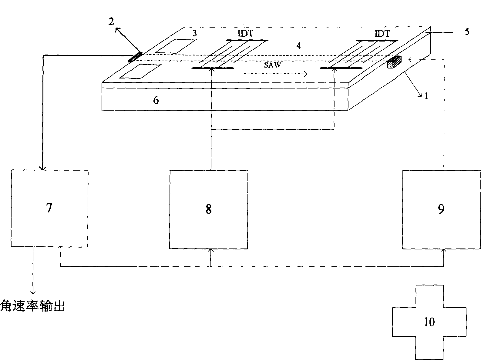
[0039]As can be seen from the figure, the entire micro-opto-electromechanical gyroscope system is composed of an optical reader, a surface acoustic wave sensor and a signal processing system: the optical waveguide reader is composed of a laser light source 1, a light source drive circuit 9, an electro-optical waveguide modulator 3 and a photoelectric The detector 2 is composed; the surface acoustic wave sensor is composed of an acoustic wave drive circuit 8 and an interdigital transducer (IDT); the signal processing system 7 still adopts an electrical signal processing method. The entire micro-opto-electromechanical gyroscope system is integrated on an integrated chip with lithium niobate crystal as the substrate material 6, and the substrate size is 20×10×1mm. A semiconductor laser 1 (FLMM-0808-7*1-1.5W) with a wavelength of λ=808nm is driven by a light source drive circuit 9, and is bonded to a photodetector 2 (PIN21112) at both ends of an optical waveguide 4 with a central w...


PUM


Abstract

The invention relates to a device of testing the rotation angular speed, relating to the acoustic wave technique, especially providing a micro optical mechanical gyroscope, wherein it is formed by laser source, acoustic surface wave sensor, optical waveguide, electric optical modulator, detector and signal processing system; it is characterized in that: it uses refractive optical signal to measure the angular speed of gyroscope rotation; the interdigital transducer (IDT) generates acoustic surface wave to change the refractive index of medium to form density grid, to refract the optical transmitted in waveguide on the acoustic grid; since the matter will generate Ge force when rotation to change the frequency characteristic parameter of acoustic wave; and the detector receives the first refracted light, to read out the angular speed sensitive to the Ge force from the changes of light intensity and phase. The invention can resist to vibration and electromagnetic interference, with wide temperature application and higher accuracy then present MEMS gyroscope, to test the inertia test unit.

Description

Technical field: [0001] The invention relates to a micro-miniature inertial measurement device, in particular to a micro-optical electromechanical gyroscope. Background technique: [0002] The inertial navigation system (INS) is a key part of automatic navigation, positioning, orientation, and stability systems. Since its birth in the 1920s, it has occupied a dominant position in the fields of navigation, attitude control, etc., and the gyroscope is exactly the measurement in the inertial system. The core component of angular velocity. [0003] In recent years, in the inertial navigation device market, optical gyroscopes and micromechanical gyroscopes are more comprehensively superior in terms of convenience and price. Various experiments have proved that they have greater application advantages than mechanical gyroscopes, electrostatic gyroscopes, and magnetoelectric gyroscopes. Among optical gyroscopes, laser gyroscopes have an advantage in high-precision applications an...

Claims


Application Information

Patent Timeline
Patent Type & Authority Applications(China)
IPC IPC(8): G01C19/02G01C19/42G01P9/02
CPCB81C99/005
Inventor 陈淑芬赵毅付雷邹正峰孟彦彬
Owner BEIJING INSTITUTE OF TECHNOLOGYGY
Why Eureka
Try Eureka