
Work-cold joint supplied cross still state straight and reverse coupling heating power circulation system and method

A thermodynamic cycle system and co-supply technology, applied in the field of energy, can solve the problems of high exhaust temperature of heat source, increase irreversible loss in the condensation process of power cycle, waste of pressure energy, etc., to increase the concentration of mixed working medium and improve temperature matching situation, the effect of improving the effective utilization rate

Active Publication Date: 2007-04-18
中科思道(南京)储能技术有限公司
View PDF1 Cites 13 Cited by
  • Summary
  • Abstract
  • Description
  • Claims
  • Application Information

AI Technical Summary

Problems solved by technology

[0008] 1. Unreasonable utilization of heat source energy: In heat exchangers (such as waste heat boilers, reboilers, etc.) heated by external heat sources, the flow of heat sources cannot be adjusted according to the principle of energy cascade utilization according to the requirements of different temperature levels of working fluids. Reasonable configuration, but most of them use a single heat source to heat the working fluid in the waste heat boiler and reboiler and then discharge it directly into the environment.
[0009] 2. The adverse effect of the characteristics of the mixed working fluid on the condensation process of the power cycle: Compared with the single working fluid, the variable temperature condensation of the mixed working fluid increases the irreversible loss of the condensation process of the power cycle, and at the same time makes the turbine exhaust pressure increase relatively. high
Although the existing forward and reverse coupled cycles have adopted some measures to alleviate this problem to a certain extent, the condensation process is still one of the main sources of exergy loss in the entire cycle, and it is the main reason that restricts the performance of the mixed working fluid coupled cycle.
[0010] 3. Waste of pressure energy (exergy) in the system: In the conventional ammonia absorption refrigeration reverse cycle, throttling valves are used in many places to achieve the required pressure drop, making the corresponding pressure energy (exergy) lost in vain

Method used


Image

  • Work-cold joint supplied cross still state straight and reverse coupling heating power circulation system and method
  • Work-cold joint supplied cross still state straight and reverse coupling heating power circulation system and method
  • Work-cold joint supplied cross still state straight and reverse coupling heating power circulation system and method

Examples


Embodiment 1

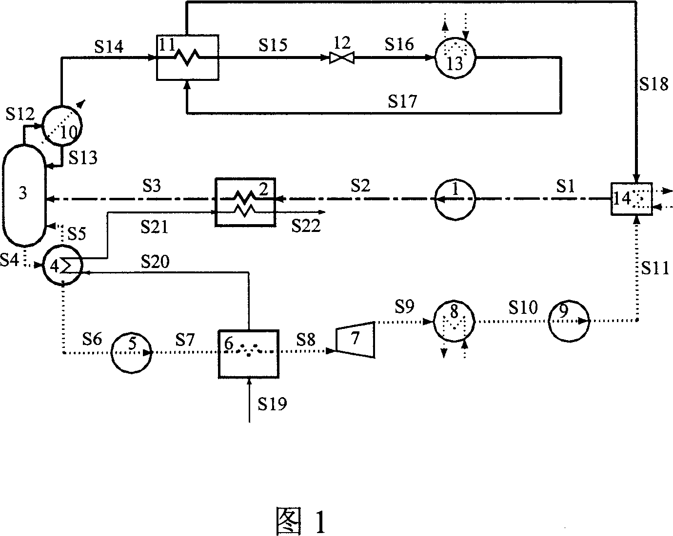
[0044] The present embodiment system consists of pumps 1, 5, 9, heat exchanger 2, rectification tower 3 (including tower bottom reboiler 4 and tower top condenser 10), waste heat boiler 6, steam turbine 7, condenser 8, Cooler 11, throttle valve 12, evaporator 13, and absorber 14. The specific process is:

[0045] In the refrigeration reverse cycle, the basic concentration of ammonia water working medium S1 is boosted by pump 1, and heat exchanger 2 is heated to saturated liquid S3 and sent to rectification tower 3 to split into dilute ammonia solution S4 and concentrated ammonia vapor S12.

[0046] After the concentrated ammonia vapor S12 is completely condensed by the tower top condenser 10, S13 is refluxed in the rectification tower, and S14 is used as a refrigerant solution to obtain a low-temperature concentrated ammonia solution S16 after being supercooled by the cooler 11 and throttling and reducing pressure by the throttle valve 12. Then it is sent to the evaporator 13...

Embodiment 2

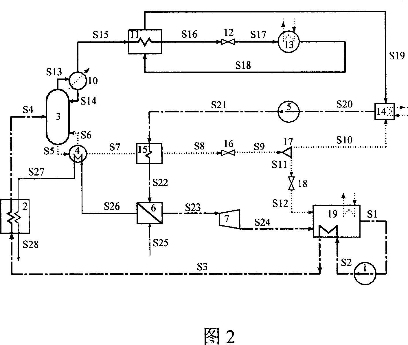
[0050] The system of this embodiment consists of pumps 1, 5, heat exchangers 2, 15, rectification tower 3 (including tower bottom reboiler 4 and tower top condenser 10), waste heat boiler 6, steam turbine 7, cooler 11, Throttle valves 12, 16, 18, evaporator 13, high-pressure absorber 14, flow splitter 17, and low-pressure absorber 19 form. The specific process is:

[0051] In the refrigeration reverse cycle, after the basic concentration ammonia water working medium S1 is boosted by pump 1, it absorbs heat through low-pressure absorber 19 and heat exchanger 2 to saturated liquid S4, and then sends it to rectification tower 3 to split into dilute ammonia solution S5 and concentrated ammonia solution S5. Ammonia vapor S13.

[0052] The concentrated ammonia vapor S13 is completely condensed by the tower top condenser 10, part of the concentrated ammonia liquid S14 is refluxed in the rectification tower, and the rest of the concentrated ammonia liquid S15 is used as a refrigerant...

Embodiment 3

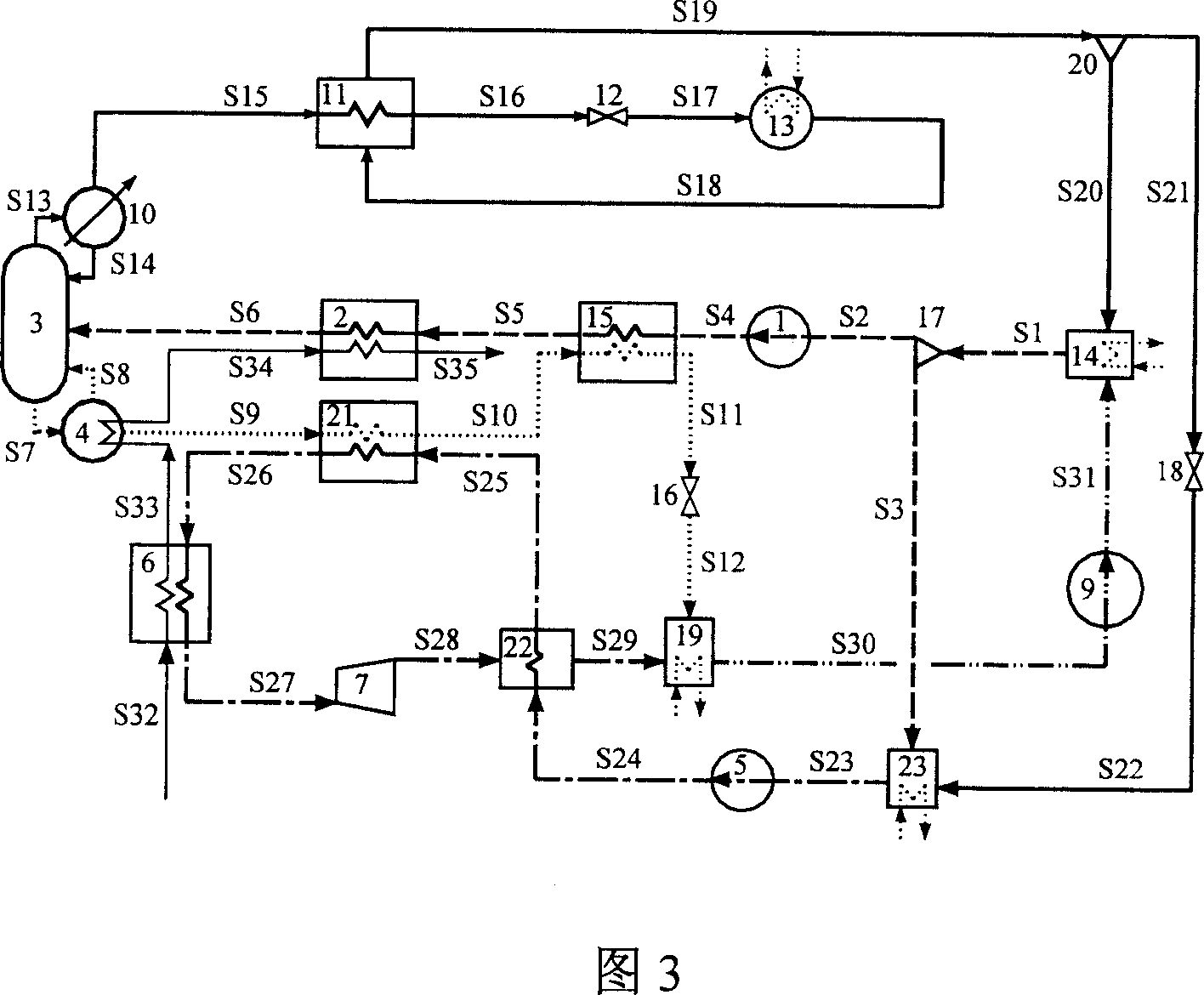
[0057] The system of this embodiment consists of pumps 1, 5, 9, heat exchangers 2, 15, rectification tower 3 (including tower bottom reboiler 4 and tower top condenser 10), waste heat boiler 6, steam turbine 7, cooler 11. Throttle valves 12, 16, 18, evaporator 13, high-pressure absorber 14, splitters 17, 20, low-pressure absorber 19, preheater 21, regenerator 22, and medium-pressure absorber 23. The specific process is as follows: in the refrigeration reverse cycle, the basic concentration ammonia water working substance S1 is divided into S2 and S3 through the flow divider 17, wherein S2 is used as the feed of the rectification tower and is boosted by the pump 1, and then heated in the heat exchangers 15 and 2 The saturated liquid S6 is sent to the rectification tower 3 and divided into dilute ammonia solution S7 and concentrated ammonia vapor S13.

[0058] The dilute ammonia solution S7 produced at the bottom of the rectification tower absorbs heat in the reboiler 4, and the...


PUM


Abstract

The invention includes the following steps: heating the ammonia water working medium to a saturated liquid state and then being separated into strong ammonia steam and weak ammonia water; using the condensated strong ammonia steam as the refrigerating output and generate the strong ammonia wet steam; mixing the weak ammonia water after the power positive circulating work with the strong ammonia wet steam and then being condensated to be the fundamental concentration ammonia water working medium.

Description

technical field [0001] The invention relates to the field of energy technology, in particular to a power-cold combined supply cross-quiescent positive and negative coupling thermodynamic cycle system and method. Background technique [0002] Thermodynamic cycle is the theoretical basis of heat engine development and the core of energy power system, and it is also an important aspect and driving force for the development of thermodynamics. The introduction of the concept of total energy system in the 1970s and 1980s made the idea of ​​thermodynamic cycle research no longer limited to the advantages and disadvantages of a single cycle or process, but paid more attention to the exploration of various high-performance combined cycles that combine different cycles organically, so that the energy The transformation utilizes the process to improve to the system level to understand. The temperature ranges of the power positive cycle and the refrigeration reverse cycle are respectiv...

Claims


Application Information

Patent Timeline
IPC IPC(8): F25B15/04F01K7/00
CPCY02B30/62Y02A30/27
Inventor 张娜刘猛蔡睿贤诺姆·里奥
Owner 中科思道(南京)储能技术有限公司
Learn More